Conditions for constructive and destructive interference of waves from two sources (13-15)
Question
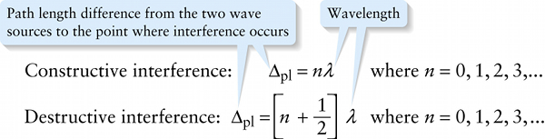
Path length difference from the two wave sources to the point where interference occurs
{"title":"Path length difference from the two wave sources to the point where interference occurs","description":"Correct!","type":"correct","color":"#99CCFF","code":"[{\"shape\":\"poly\",\"coords\":\"82,133\"},{\"shape\":\"rect\",\"coords\":\"10,16,12,16\"},{\"shape\":\"rect\",\"coords\":\"139,5,151,16\"},{\"shape\":\"rect\",\"coords\":\"119,28,128,43\"}]"} {"title":"Wavelength","description":"Wrong","type":"incorrect","color":"#993300","code":"[{\"shape\":\"rect\",\"coords\":\"172,2,183,16\"},{\"shape\":\"rect\",\"coords\":\"184,30,197,43\"}]"}Review
If the path length difference Δplis neither a whole number of wavelengths nor an odd number of half-wavelengths, the interference is neither completely constructive nor completely destructive (Figure 13-10c). Because interference of the surface waves occurs at all points in Figure 13-11, we call the overall pattern in that figure an interference pattern.
Here’s a summary of the conditions that must be met for constructive and destructive interference:
(Note that for constructive interference, n=0 refers to the case where there is zero path length difference, so the two waves naturally arrive in phase. This is the situation for the center yellow dot in Figure 13-11.)