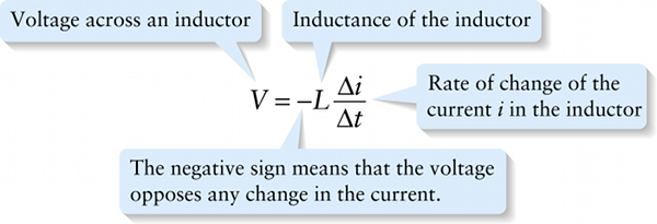
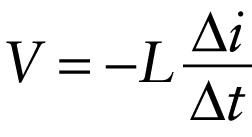
Voltage across an inductor (21-16)
Question
The negative sign means that the voltage opposes any change in the current.
{"title":"Voltage across an inductor","description":"Wrong","type":"incorrect","color":"#99CCFF","code":"[{\"shape\":\"poly\",\"coords\":\"82,133\"},{\"shape\":\"rect\",\"coords\":\"10,16,12,16\"},{\"shape\":\"poly\",\"coords\":\"144,22\"},{\"shape\":\"rect\",\"coords\":\"4,35,48,87\"}]"} {"title":"Inductance of the inductor","description":"Incorrect","type":"incorrect","color":"#ffcc00","code":"[{\"shape\":\"rect\",\"coords\":\"138,37,176,87\"}]"} {"title":"Rate of change of the current i in the inductor","description":"Wrong","type":"incorrect","color":"#333300","code":"[{\"shape\":\"rect\",\"coords\":\"180,11,251,123\"}]"} {"title":"The negative sign means that the voltage opposes any change in the current.","description":"Correct!","type":"correct","color":"#000080","code":"[{\"shape\":\"rect\",\"coords\":\"104,55,139,77\"}]"}Review
Let’s examine Equation 21-16 to see what it means. In Figure 21-5a an inductor (symbolized by a coil) carries a constant current i. The rate of change of this constant current is zero, so from Equation 21-16 there is zero voltage across the inductor V=0. (Remember, we are ignoring the resistance of the wires that make up the inductor.) In Figure 21-5b the current through the inductor increases, so in Equation 21-16 Δi/Δt>0 and V<0. The negative value of V means that there is a voltage drop from where the current enters the inductor to where it leaves the inductor. That’s like the voltage drop for current that passes through a resistor, which means that the inductor is now resisting the current—or, more properly, resisting the increase in current. So in this case the voltage opposes the change in current. In Figure 21-5c the current through the inductor decreases, so in Equation 21-16 Δi/Δt<0 and V>0. The positive value of V means that there is a voltage gain from where the current enters the inductor to where it leaves. That’s like the voltage gain for current directed through a battery (a source of emf) from the negative terminal to the positive terminal, so in this case the inductor is assisting the current and so is trying to prevent the current from decreasing. Again, the voltage opposes the change in current.

