Optics and Telescopes
 Since the time of Galileo, astronomers have been designing instruments to collect more light than the human eye can gather on its own. Collecting more light enables us to see things more brightly, in more detail, and at a greater distance. There are two basic types of telescopes—those that collect light through lenses, or refracting telescopes, and those that collect it from mirrors, or reflecting telescopes (reflectors). The earliest telescopes, such as Galileo’s, used lenses, which have a variety of shortcomings as light-gathering devices. Consequently, all modern research telescopes use mirrors to collect light. Lenses are still used in the eyepieces of all home telescopes to straighten the gathered light, so when we look through these telescopes directly, our brains can accurately interpret what we see. Lenses are also used to collect light in binoculars and cameras. Reflecting and refracting telescopes have the same main purpose—to collect as many photons as possible so we can better observe the sky (see Section 3-6). Because astronomers exclusively use reflecting telescopes, we will begin exploring telescopes by discussing how these telescopes work. Then we will consider how lenses collect light, how refracting telescopes work, and, finally, how astronomers have developed telescopes to see nonvisible electromagnetic radiation.
3-5 Reflecting telescopes use mirrors to concentrate incoming starlight
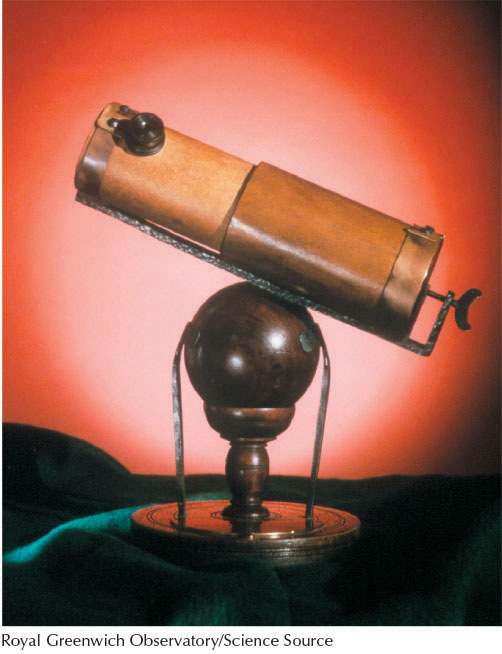
The first reflecting telescope was built in the seventeenth century by Isaac Newton (Figure 3-8). To understand how these telescopes work, consider a flow of photons, more commonly called a light ray, moving toward a flat mirror. In Figure 3-9a, a light ray strikes the mirror, and we imagine a perpendicular line coming out of the mirror at that point. According to the principle of reflection, the angle between the incoming light ray and the perpendicular (dashed line) is always equal to the angle between the outgoing, reflected light ray and that perpendicular. This principle is often stated as, “The angle of incidence equals the angle of reflection.” This rule also applies if the mirror is curved (Figure 3-9b).
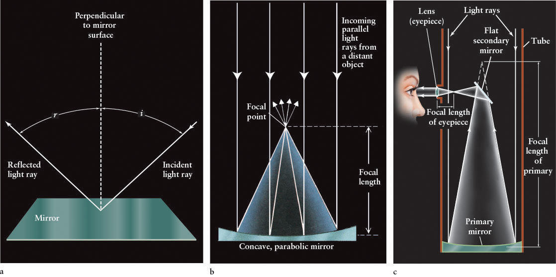
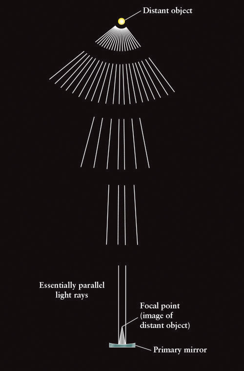
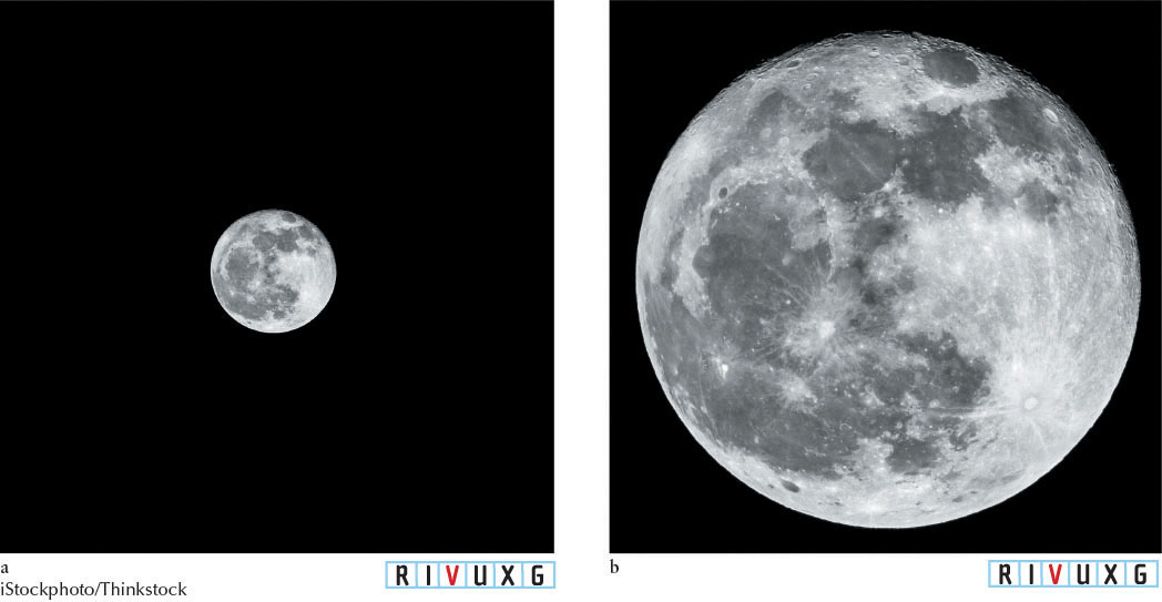
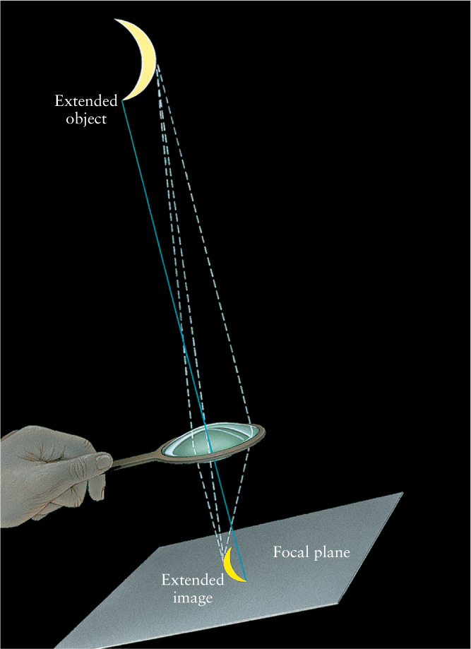
Using this principle, Newton determined that a concave (hollowed-out) mirror, ground in the shape of a parabola, causes all parallel incoming light rays that strike the mirror to converge to a focal point (Figure 3-9b). The distance between this primary mirror and the focal point, where the image of the distant object is formed, is called the focal length of the mirror. Focal points exist for light from sources that are extremely far away, like the stars. (Figure 3-10 shows why stars can be considered “far away.”) If the object is larger than a point, like the Moon or a planet, then the light will converge to a plane, called the focal plane, located at the distance of the focal length. Likewise, point objects like stars that are near each other on the celestial sphere also come into focus near each other on the focal plane.
78
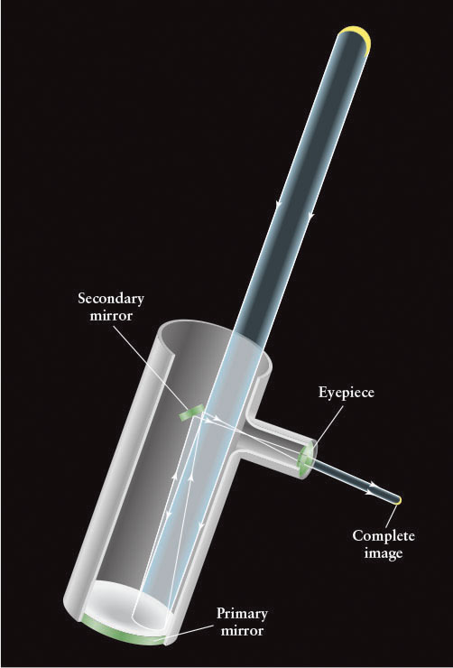
To view the image, Newton placed a small, flat mirror at a 45º angle between the primary mirror and the focal point, as sketched in Figure 3-9c and Figure 3-11a. This secondary mirror reflects the light rays to one side of the telescope, and the viewer observes the image through an eyepiece lens. We will discuss how this lens works in Section 3-8. A telescope with this optical design is still called a Newtonian reflector. Suffice it to say for now that research telescopes do not use eyepieces. As we will see shortly, light-sensitive detectors are placed in their focal planes instead.
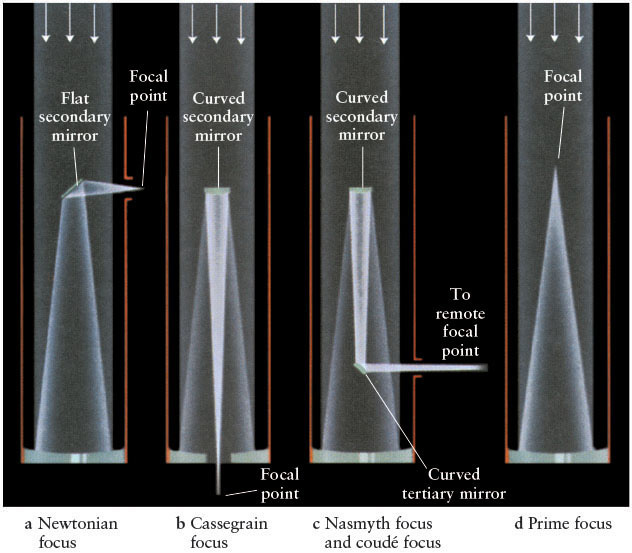
 Reflecting Telescopes Four of the most common optical designs for reflecting telescopes: (a) Newtonian focus (popular among amateur astronomers), and the three major designs used by researchers—(b) Cassegrain focus, (c) Nasmyth focus and coudé focus, and (d) prime focus.
Newtonian telescopes are popular with amateur astronomers because they are convenient to use while the observer is standing up. However, they are not used in research observatories because they are lopsided. If astronomers attach their often heavy and bulky research equipment onto the side of a Newtonian telescope, the telescope twists and distorts the image in unpredictable ways. Making matters worse, these distortions change as the telescope tracks stars across the sky and therefore tilts at different angles.
Three basic designs exist for the reflecting telescopes used in research: Cassegrain, Nasmyth/coudé, and prime focus telescopes. In the first, a hole is drilled directly through the center of the primary mirror. A convex (outwardly curved) secondary mirror placed between the primary mirror and its focal point reflects the light rays back through the hole (Figure 3-11b). This design is called the Cassegrain focus, after a 1672 design by Laurent Cassegrain (1629–1693). This secondary mirror extends the telescope’s focal length. Compact, relatively low-weight equipment is bolted to the bottom of the telescope, and the light is brought into focus in it. The advantage of this design over Newtonian telescopes is that the attached equipment is balanced and does not distort the telescope frame and, hence, the image.
The second design that astronomers use has two variations, both of which use a third mirror to direct light out the side of the telescope, at the place where it pivots (Figure 3-11c). Heavier or bulkier optical equipment that requires firmer mounting can be located at the Nasmyth focus, after Scottish engineer James Nasmyth (1808–1890), who developed it. If an extremely long focal length is desired, a coudé focus (named after a French word meaning “bent like an elbow”) is used. Equipment that profits from the use of the Nasmyth focus and coudé focus includes a variety of spectrographs, instruments that separate light from objects into its individual colors to determine the objects’ chemistries, surface temperatures, and motions toward or away from us.
79
In the third design, an observing device is located at the undeflected focal point, directly in front of the primary mirror. This arrangement is called the prime focus (Figure 3-11d). This design has the advantages of making the brightest image (for a given exposure time) and having no secondary mirror, having the fewest reflections that otherwise would cause light loss and distortion.
The earliest telescopes were ground from a metal alloy called speculum metal that polished to a bright surface. However, it reflected only about two-thirds of the light that struck it and it tarnished rapidly. Modern primary telescope mirrors today are made from glass, which maintains its shape well. A highly reflective aluminum coating is applied to the top surface of the mirror after it is ground and polished to the appropriate shape. In this design, the light never enters the mirror, unlike the mirrors we use in everyday life, with the reflective coating behind the glass.
3-6 Secondary mirrors dim objects but do not create holes in them
You have probably noticed (see Figure 3-11) that the secondary mirror of a reflector blocks some incoming light—one unavoidable price that astronomers must pay. Typically, a secondary mirror prevents about 10% of the incoming light from reaching the primary mirror. This problem is addressed by constructing primary mirrors with sufficiently large surface areas to compensate for the loss of light. You might also think that, because light is missing from the center of the telescope due to blockage by the secondary mirror, a corresponding central “hole” appears in the images. However, this problem does not occur, because light from all parts of each object being observed enters all parts of the telescope (Figure 3-12). Indeed, covering any part of the primary mirror darkens the image but does not limit which parts of the object you can see through the telescope. Likewise, blocking part of the opening of a telescope made just with lenses darkens the image but does not create a hole in the image.
80
3-7 Telescopes brighten, resolve, and magnify
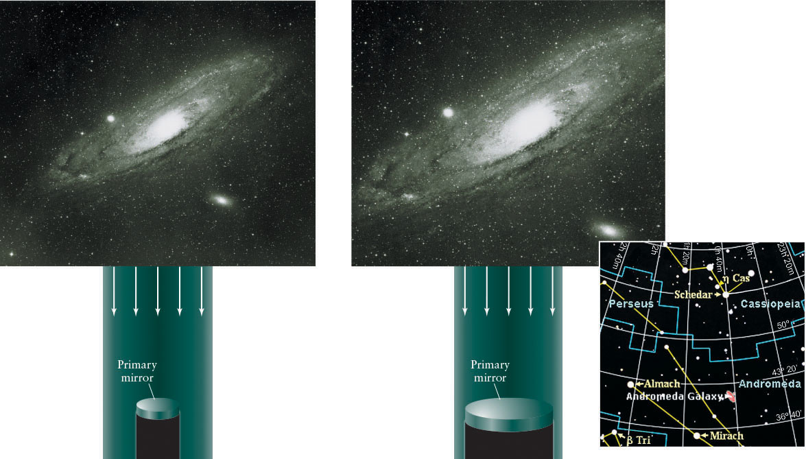
As mentioned earlier, a telescope’s most important function is to provide astronomers with as bright an image as possible. The brighter an object appears, the more information about it we can extract. The observed brightness of any object depends on the total number of photons collected from it, which, in turn, depends on the area of the telescope’s primary mirror. Analogously, the pupils in our eyes get larger in dark environs to allow more photons to strike the retina and create a brighter image than otherwise. For exposures of equal times, a telescope with a large primary mirror produces brighter images and detects fainter objects than a telescope with a smaller primary mirror (Figure 3-13).
Insight Into Science: Costs and Benefits
Science now relies heavily on technology to conduct experiments or to make observations. The cost of cutting-edge astronomical observations may run to hundreds of millions of dollars or more. The return on such investments is a better understanding of how the universe works, how we can harness its resources, and our place in it.
The light-gathering power of a telescope is directly related to the area of the telescope’s primary mirror. Recall that the area and diameter of a circle are related by the formula

where d is the diameter of the mirror and π (pi) is about 3.14. Consequently, a mirror with twice the diameter of another mirror has 4 times the area of the smaller mirror and, therefore, collects 4 times as much light as does the smaller one in the same amount of time. For example, a 36-cm-diameter mirror has 4 times the area of an 18-cm-diameter mirror. Therefore, the 36-cm telescope has 4 times the light-gathering power of a telescope half its size.
Another vital function of any telescope is to reveal greater detail of objects that are more than just points of light. Such extended objects include the Moon, the Sun, planets, galaxies, interstellar gas clouds, and clusters of stars, among other things. A large telescope increases the sharpness of the image and the degree of detail that can be seen. Angular resolution (often just called resolution) measures the clarity of images (Figure 3-14). The angular resolution of a telescope is measured as the arc angle between two adjacent stars whose images can just barely be distinguished by the telescope. The smaller the angle, the sharper the image. Large, modern telescopes, like the Keck telescopes in Hawaii, have angular resolutions better than 0.1 arcsec. As a general rule, a telescope with a primary mirror twice the diameter of another telescope’s primary will be able to see twice as much detail as the smaller telescope.
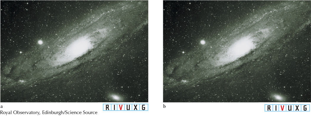
The final function of a telescope is to make objects appear larger. This property is called magnification. Magnification is associated with resolution, because the larger the image, the more detail of the image you can potentially see (Figure 3-15). The magnification of a reflecting telescope is equal to the focal length of the primary mirror divided by the focal length of the eyepiece lens
81
82
For example, if the primary mirror of a telescope has a focal length of 100 cm and the eyepiece has a focal length of 0.5 cm, then the magnifying power of the telescope is

This property is usually expressed as 200×.
Margin Question 3-4
Question
Normal eyeglasses or contact lenses are designed to improve which aspect of vision presented in this section?
Eyepieces are removable. Eyepieces with different focal lengths change a telescope’s magnification. However, there is a limit to the magnification of any telescope. Try to magnify beyond that limit, and the image becomes distorted. As a rule, a telescope with a primary mirror twice the diameter of another telescope’s primary will have twice the maximum magnification of the smaller telescope.
3-8 Eyepieces, refracting telescopes, and binoculars use lenses to focus incoming light
Although light travels at about 300,000 km/s in a vacuum, it moves more slowly through any medium, such as glass. As light enters the glass, it slows abruptly, much like a person walking from a hard pavement onto a sandy beach. Conversely, light that exits a piece of glass resumes its original speed, just as a person resumes his or her normal pace when stepping back from sand onto a solid surface.
As a result of changing speed, light also changes direction as it passes from one transparent medium into another. As noted earlier, this latter change is called refraction. You see refraction every day when looking through windows. Imagine a stream of photons from a star that enters a window, as shown in Figure 3-16a. As a light ray goes from the air into the glass, the light ray’s direction changes so that it is more perpendicular to the surface of the glass than it was before entering. Once inside the glass, the light ray travels in a straight line. Upon emerging from the other side, the light ray bends once again, resuming its original direction and speed. The net effect is only a slight, uniform displacement of the objects beyond the glass.
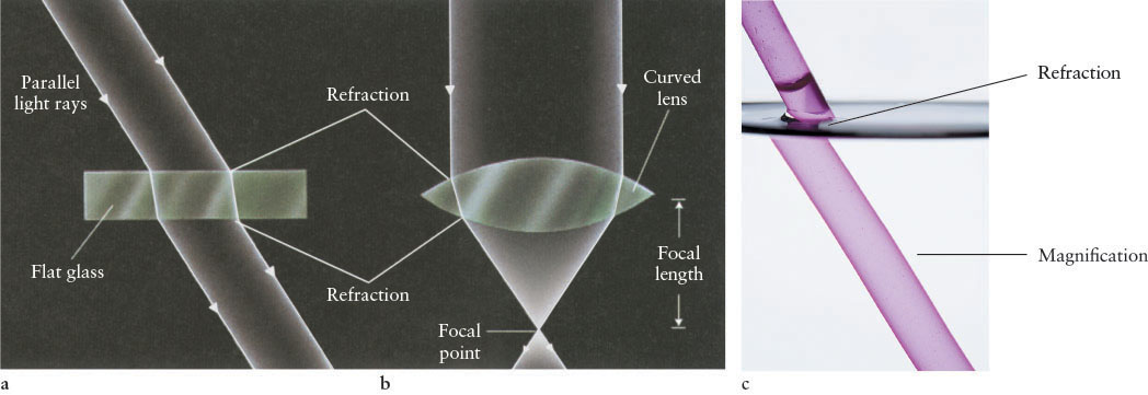
Unlike windows, lenses have surfaces of varying thickness (Figure 3-16b). These curved surfaces force the light rays to emerge from the lens in different directions than they had before entering the lens. Lenses that are thicker at their centers than at their edges are called convex lenses and force the light that enters them to converge as it passes through. Conversely, lenses thinner at their centers than around their edges are called concave lenses. They cause light rays to diverge.
Large convex lenses called objective lenses were used instead of primary mirrors in research telescopes in the nineteenth century (and are still used in many telescopes built for home use today). Parallel light rays that enter an objective lens converge and meet at the focal point of the lens. The distance between the focal point and the lens is the lens’s focal length (see Figure 3-16b). As with reflecting telescopes, if the object is close enough or large enough to be more than just a dot as seen through the telescope, all the light from it does not converge at the focal point, but rather focuses along the focal plane (Figure 3-17). When we want to look directly into the telescope, a small eyepiece lens is used to bring the light rays collected by the objective lens back to being parallel, so our brains can make sense of what we see.
83
A refracting telescope or refractor (Figure 3-18) is therefore an arrangement of two lenses used to gather light. The objective lens at the top of the telescope has a large diameter and long focal length. Like a primary mirror, its purpose is to collect as much light as possible. The eyepiece lens, at the bottom of the telescope, is smaller and has a short focal length. The mathematics of magnification for a refracting telescope is the same as for a reflecting telescope with the focal length of the objective lens replacing the focal length of the primary mirror. Likewise, all of the rules for the limits on telescopes are the same for refractors as for reflectors.
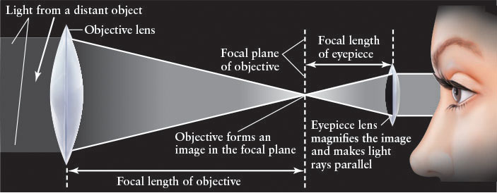
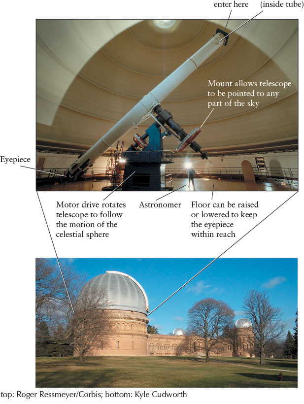
 Essentials of a Refracting Telescope A refracting telescope consists of a large, long-focal-length objective lens that collects and focuses light rays and a small, short-focal-length eyepiece lens that restraightens the light rays. The lenses work together to brighten, resolve, and magnify the image formed at the focal plane of the objective lens.
The largest refracting telescope in the world, completed in 1897 and located at the Yerkes Observatory in Williams Bay, Wisconsin, near Chicago (Figure 3-19), has an objective lens that is 102 cm (40 in.) in diameter with a focal length of 19⅓ m (63½ ft). The lens was ground by the premier American lensmaker of the nineteenth century, Alvan Clark (1804–1887). The second-largest refracting telescope, located at Lick Observatory near San Jose, California, has an objective lens of 91 cm (36 in.) in diameter. No major refracting telescopes were constructed in the twentieth century or are planned for this century.
84
Refracting telescopes suffer from a variety of problems that have limited their use as research instruments. These problems include the following:
 It is difficult to grind a lens to the very complicated shape necessary to have all parallel light rays of any color passing through it converge to the same focal point. When, for example, the lens is given a spherical shape (relatively easy to manufacture), the light at different distances from the center of the lens has different focal lengths (Figure 3-20). This phenomenon is called spherical aberration. Such aberration does not occur for reflecting telescopes because the shape of a mirror needed to focus light from every part of the mirror to the same focal point is a simple parabola, which is easy to manufacture, as discussed in Section 3-9.
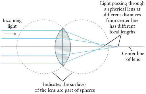 Figure 3-20: The Geometry of a Spherical Lens If both sides of a lens are spherical surfaces, as shown here, then light rays of the same color passing through at different distances from the center of the lens are refracted by different amounts. Therefore, spherical lenses have different focal lengths for these different light rays and so they give blurry images.
-
Even when light passes through an ideally shaped lens, different colors of light are refracted by different amounts, so they have different focal lengths. This phenomenon is called chromatic aberration (Figure 3-21a). As a result of spherical and chromatic aberration, objects look blurred (Figure 3-21b). Chromatic and spherical aberration can be corrected (Figure 3-22) by adding a second lens with a different shape and made of a different type of glass (which refracts light by a different amount than does the first lens). Chromatic aberration is not a problem for reflectors because the reflecting surface is always on the top of the mirror; reflecting telescopes do not use refraction to focus light.
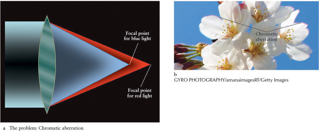 Figure 3-21: RIVUXG Chromatic Aberration (a) Light of different wavelengths is refracted by different amounts when passing through a medium such as glass. Therefore, single lenses such as this one have different focal lengths for light of different colors passing through them. (b) Image showing chromatic aberration. Note the different colors on the edges of the petals caused by light passing through a lens.
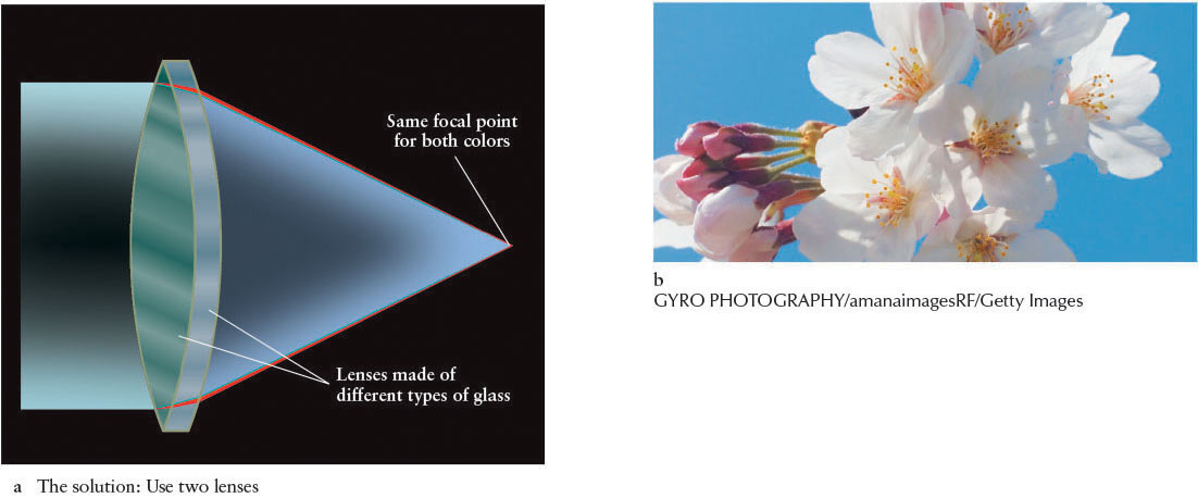 Figure 3-22: RIVUXG Achromatic Lens (a) By using two differently shaped lenses (often of different types of glass), light of different wavelengths can be brought into focus at the same focal length. Such achromatic lenses are used in cameras and many telescopes. (b) Same object as in Figure 3-21b imaged through an achromatic lens. Note that the colors on the edges of the petals seen in Figure 3-21b do not occur here.
 -
A lens must be supported only around its edges to avoid blocking the light. The weight of a large lens can cause it to sag and thus distort the image. This distortion is not a problem with reflectors because the entire underside of the mirror can be supported, as necessary.
-
Air bubbles in the glass cause unwanted refractions and, hence, distorted images.
-
Glass does not allow all wavelengths to pass through it equally.
Margin Question 3-5
Question
How do human eyes focus light?
 These last two points are not issues with reflectors because the light never enters the glass. The combination of all the problems listed here makes images from refractors less accurate than those obtained from reflecting telescopes, which explains why modern research telescopes are all reflectors. The mirrored surfaces of research telescopes are polished so smoothly that the highest bumps are less than 0.002 times the thickness of a human hair.
Although they are better light collectors than refracting telescopes, reflecting telescopes are not perfect; there are several prices to pay for the advantages they offer over refractors. Two of the most important prices to pay are blocked light, as discussed in Section 3-6, and spherical aberration, which we consider in the next section.
86
3-9 Shaping telescope mirrors and lenses is an evolving science
To make a reflector, an optician traditionally grinds and polishes a large slab of glass into a concave, spherical surface. Before computer control, grinding a spherical surface was much easier than grinding the ideal parabolic surface. However, light that enters a spherical telescope mirror at different distances from the mirror’s center comes into focus at different focal lengths (Figure 3-23a). Images taken directly from such telescopes have the same spherical aberration as the refractors described above.
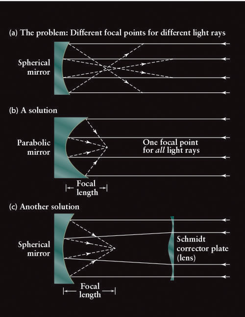
We can avoid spherical aberration in reflecting telescopes by making the mirror parabolic (Figure 3-23b) or by using a thin correcting lens, called a Schmidt corrector plate, with a spherical mirror. Developed in 1930 by the Estonian-Swedish optician Bernhard Schmidt (1879–1935), the corrector plate is located at the top of the telescope (Figure 3-23c). The light coming into the telescope is refracted by the plate just enough to compensate for spherical aberration and to bring all of the light into focus at the same focal length. These correctors have the added benefit of focusing light from a larger angle in the sky than would be in focus without the plate. A Schmidt corrector plate enables astronomers to map large areas of the sky with relatively few photographs at moderately high magnification. In other words, the Schmidt corrector plate acts like a wide-angle lens on a camera. Schmidt corrector plates are often used in conjunction with Cassegrain mirrors to create Schmidt-Cassegrain telescopes, which are popular for home use because they are compact and give relatively wide-angled images. However, the plate does not allow for as much magnification as a telescope with a parabolic mirror. (If you are interested in learning about telescope mounts or the related matter of buying a telescope, see Appendix H.)
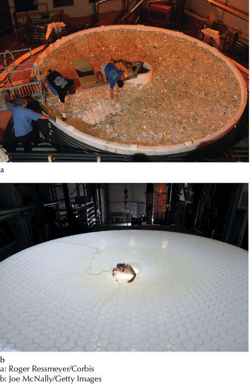
Although some parabolic primary mirrors have been meticulously hand-ground over the past century, the advent of computer-controlled grinding and rotating furnaces (Figure 3-24), in which the liquid glass is actually spun into a parabolic shape, has now made it economical to cast parabolic mirrors with diameters of several meters. That spinning a liquid causes it to develop a parabolic surface was discovered by Isaac Newton in 1689, when he created the effect in a bucket of spinning water.
87
3-10 Storing and analyzing light from space is key to understanding the cosmos
The invention of photography during the nineteenth century was a boon for astronomy. By taking a long exposure with a camera mounted at the focal plane of a telescope, an astronomer could record extremely faint features that could not be seen by just looking through the telescope. The reason photography is better is that our nervous system refreshes (that is, replaces) the images we receive from our eyes several times a second, whereas film adds up the intensity of all the photons that affect its emulsion. By keeping telescopes aimed precisely, so that images do not blur, exposures of an hour or more became quite routine. Astrophotographs and their modern electronic equivalents, discussed in the next few paragraphs, make all objects appear brighter and reveal greater detail in extended objects—such as galaxies, star clusters, and planets—than we could otherwise see.
Margin Question 3-6
Question
Why do the human eye and brain clear the images that they receive many times per second?
Astronomers have long known, however, that a photographic plate is an inefficient detector of light because it depends on a chemical reaction to produce an image. Typically, only 2% of the light striking film triggers a reaction in the photosensitive material. Thus, roughly 98% of the light falling onto a photographic plate is wasted.
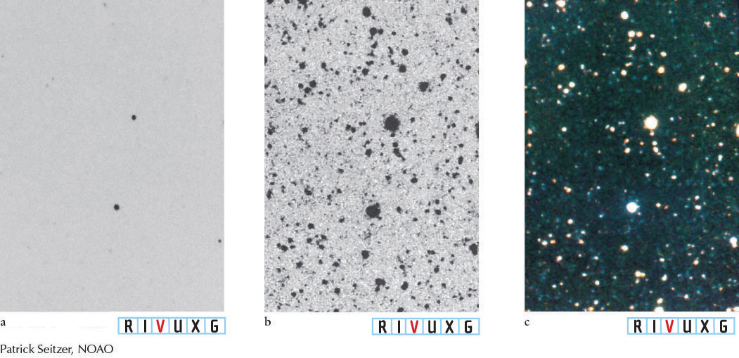
Rapidly evolving technology has changed all that. We have replaced photographic film with highly efficient electronic light detectors called charge-coupled devices (CCDs). Very good CCDs respond to between 50% and 75% of the light falling on them; great CCDs are sensitive to more than 90% of the photons that strike them. Clearly CCD resolution is much better than that of film, and CCDs respond more uniformly to light of different colors. Divided into an array of small, light-sensitive squares called picture elements or, more commonly, pixels, each CCD is a square or rectangle a few centimeters on a side. Several of them are often used together to create a larger image (Figure 3-25). Digital cameras and picture-taking cell phones use this same CCD technology. The largest grouping of CCDs used on a telescope has 400 megapixels (a megapixel is 1 million pixels), compared to most digital cameras, which typically have between 12 and 24 megapixels.
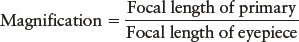
When an image from a telescope is focused on the CCD, an electric charge builds up in each pixel in direct proportion to the intensity of the light (number of photons) falling on that pixel. When the exposure is finished, the charge on each pixel is read into a computer. Figure 3-26 shows one photograph and two CCD images of the same region of the sky, all taken with the same telescope. You can see how many details visible in the CCD images are absent in the ordinary photograph.
88
3-11 Earth’s atmosphere hinders astronomical research
Earth’s atmosphere affects the light from objects in space before it reaches ground-based telescopes. Even for those wavelengths that have windows through the atmosphere (see Section 3-4), some light is absorbed in the atmosphere, making all objects appear dimmer than they would appear from space. Also, the air is turbulent and filled with varying amounts of impurities and moisture. You have probably seen turbulence while driving in a car on a hot day, when the road ahead appears to shimmer. Blobs of air, heated by Earth, move upward to create this effect. Light passing through such a blob is refracted, because each hot air mass has a different density than the cooler air around it. Because each blob behaves like a lens, images of objects beyond them appear distorted.
 The atmosphere over our heads is similarly moving and changing density, and the starlight passing through it is similarly refracted. Because air density changes rapidly, the resulting changes in refraction make the stars appear to change brightness and position rapidly, an effect we see as twinkling. When photographed from Earth for more than a few seconds, twinkling smears out a star’s image, causing it to look like a disk rather than a pinpoint of light (Figure 3-27a). Astronomers use the expression “seeing” to describe how steady the atmosphere is; when the seeing is bad, much twinkling is occurring and, therefore, telescopic images are spread out and blurry.

The angular diameter of a star’s smeared-out image, called the seeing disk, is a realistic measure of the best possible resolution. The size of the seeing disk varies from one observatory site to another. At Palomar Observatory in California, the seeing disk is roughly 1 arcsec (1″). The best conditions on Earth have been recorded at the observatory on the 14,000-ft summit of Mauna Kea, the tallest volcano on the island of Hawaii. The seeing disk there has been as small as 0.2″.
Without the effects of Earth’s atmosphere, stars do not twinkle. As a result, photographs taken from telescopes in space reveal stars as much finer points (Figure 3-27b), and extended objects, such as planets and galaxies, appear in greater detail.
Insight Into Science: Research Requires Patience
Seeing conditions—indeed, most observing situations in science—are rarely ideal. Besides such natural phenomena, which are beyond their control, scientists must also contend with equipment failures, late deliveries of parts, and design flaws. Furthermore, because travel time is so long, some missions (like the robotic spacecraft roving on Mars or the New Horizons voyage to Pluto and the Kuiper belt) take years or even decades to complete.
Light pollution, light that comes from nonastronomical sources, poses another problem for Earth-based telescopes (Figure 3-28). Keep in mind that the larger the primary mirror, the more light it gathers and, therefore, the more information astronomers can obtain from its images or spectra. The 5-m (200-in.) telescope at the Palomar Observatory between San Diego and Los Angeles was the first truly great large telescope, providing astronomers with invaluable insights into the universe for decades. However, light pollution from the two cities now fills the night sky, seriously reducing the ability of that telescope to collect light from objects in space. Not surprisingly, the best observing sites in the world are high on mountaintops—above smog, water vapor, and clouds—and far from city lights. An even better location, astronomers have discovered, is to observe space from space, eliminating the interference of both the lights of civilization and Earth’s atmosphere. Removing these effects is why the Hubble Space Telescope and other orbiting telescopes achieve such magnificent resolution in the images they take.

Margin Question 3-7
Question
Where in a typical house can the seeing problems described in Section 3-11 be observed?
89
WHAT IF…: Stars actually twinkled?
Stars appear to significantly change their brightness (twinkle) in fractions of a second. If they actually did vary in brightness as much as we see them vary, they would do so by changing size—bigger is brighter. If such expansion and contraction occurred, the rapid motion of their gases would cause stars to blow apart in a matter of seconds.
90
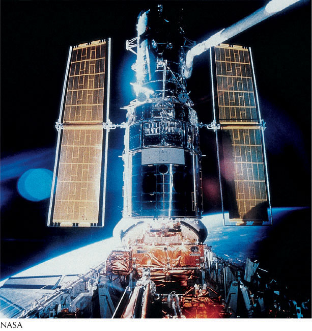
3-12 The Hubble Space Telescope provides stunning details about the universe
For decades, astronomers dreamed of observatories in space. Such facilities would eliminate the image distortion created by twinkling and by poor atmospheric transparency due to pollution, volcanic debris, and water vapor. These telescopes could operate 24/7 and over a wide range of wavelengths—from the infrared through the visible range and far out into the gamma-ray part of the spectrum. Over the past three decades, NASA and other space agencies have launched a variety of space telescopes, including four of what NASA calls its Great Observatories. The first Great Observatory to go up was the Hubble Space Telescope (HST).
Soon after HST was placed in orbit from the space shuttle in 1990, astronomers discovered that the telescope’s 2.4-m primary mirror had been ground to the incorrect shape. Therefore, it suffered from spherical aberration, which caused its images to be surrounded by a hazy glow. During a repair mission in December 1993, astronauts installed corrective optics that eliminated the problem (Figure 3-29). The telescope was further upgraded in 1997, 1999, 2002, and 2009. Now HST has a resolution of better than 0.1″, which is better than can be obtained by telescopes on Earth’s surface without the use of advanced technology (see Section 3-13).
The observations taken by HST continue to stagger the imagination. Hubble has made discoveries related to the planets in our solar system, planetary systems around other stars, other galaxies and the distances to them, black holes, quasars, the formation of the earliest galaxies, the age of the universe, and many other topics.
3-13 Advanced technology is spawning a new generation of superb ground-based telescopes
The clarity of images taken by the HST and the “seeing” issues described earlier may suggest that ground-based observational astronomy is a dying practice. However, two exciting techniques, called active optics and adaptive optics, enable telescopes on the ground to match the quality of HST—or better it!
Historically, primary mirrors have been thick and heavy, to help keep them rigid and perfectly shaped. Nevertheless, these mirrors were not ideal because they would warp slightly as the telescope changed angle on the sky and the mirrors could not compensate for the seeing conditions, which causes the objects to move and therefore blur. However, in the 1980s, astronomers discovered that changing the shape of the primary mirror would enable them to compensate for these effects. By making thinner mirrors, the shape of the primary could be changed by pistons called actuators located under the mirror. Thus, the field of active optics was created. This technology finds the best orientation for the primary mirror in response to changes in temperature and the shape of the telescope mount. Actuators adjust the mirror every few seconds to help keep the telescope optimally aimed at its target. With active optics, the New Technology Telescope in Chile and the Keck telescopes in Hawaii routinely achieve resolutions as fine as 0.3″, whereas the resolution is much worse for telescopes without active optics at the same sites.
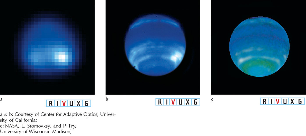
Even better resolution can be achieved with adaptive optics, which uses sensors to determine the amount of twinkling created by atmospheric turbulence. The stellar motion due to this twinkling is neutralized by computer-activated, motorized supports that actually reshape a smaller mirror installed farther down the optical path of the telescope. Adaptive optics effectively eliminates atmospheric distortion and produces remarkably clear images with resolution as fine as 0.03″ (Figure 3-30). Many large ground-based telescopes now use adaptive optics on many observing runs, resulting in images comparable to those from HST (Figure 3-30c).
Until the 1980s, telescopes with primary mirrors of between 2 and 6 m were the largest in the world. Now, new technologies in mirror building and computer control allow us to construct much larger telescopes. At least 85 reflectors around the world today have primary mirrors measuring 2 m or more in diameter. Among these are 14 reflectors that have mirrors between 8 and 10.4 m in diameter, with at least 8 other very large telescopes under construction. Appendix G contains a list of the telescopes 2 m in diameter and larger that are in operation.
91
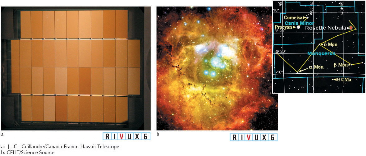
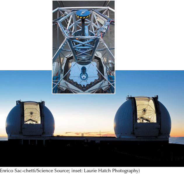
Because the cost of building very large mirrors is enormous, astronomers have devised less expensive ways to collect the same amount of light. One approach is to make a large mirror out of smaller pieces, fitted together like floor tiles. The largest examples of this segmented-mirror technique are the 10.4-m Gran Telescopio Canarias in the Canary Islands, and the 10-m (400-in.) Keck I and Keck II telescopes on the summit of Mauna Kea in Hawaii. In each of these telescopes, 36 curved hexagonal mirrors are mounted side by side to collect the same amount of light as a single primary mirror of 10.4 or 10 m, respectively (Figure 3-31). Another method, called interferometry, combines images from different telescopes. For example, used together to observe the same object, the two Keck telescopes have the resolving power of a single 85-m telescope. The four 8.2-m reflectors of the Very Large Telescope at the Paranal Observatory (see the photo at the beginning of this chapter) combine to create the resolution that would come from a single telescope 200 m in diameter. This observatory has an ideal resolution of about 0.002″.
Margin Question 3-8
Question
Why are military and spy agencies around the world so interested in cutting-edge telescope technologies?
92