17.2 17.1 Binary Codes
Coded data made up of two states (or symbols) is called a binary code. Binary codes are the hidden language of computers. The Postnet code (short and long bars) and the Universal Product Code (UPC) bar code (white spaces and dark bars) explained in Chapter 16 are two examples of binary codes. Morse code (dots and dashes) and Braille (bumps and flat markings) are two more. The opinions of two critics rating movies with U for “thumbs up” and D for “thumbs down” could be conveyed by a binary code with the four messages UU, UD, DU, and DD. Fax machines, CDs, DVDs, high-definition television signals, smartphones, and space probes represent data as strings of 0s and 1s rather than the usual digits 0 through 9 and letters A through Z. In this section, we illustrate one way binary codes can be devised so that errors in the transmission of the code can be corrected.
The idea behind error-correction schemes is simple and one you often use. To illustrate, suppose that you are reading the employment section of a newspaper and you see the phrase “must have a minimum of bive years’ experience.” Instantly you detect an error because bive is not a word in the English language. Moreover, you are fairly confident that the intended word is five. Why is that? Because five is a word derived from bive by changing a single letter, and it makes the phrase understandable. In other phrases, words such as bike or give might be sensible alternatives to bive. Using the extra information provided by the context, we often are able to infer the intended meaning when errors occur.
To demonstrate the way binary error-correcting schemes work, suppose that the National Aeronautics Space Administration (NASA) sends a spacecraft to land at 1 of 16 possible landing sites on Mars. The spacecraft orbits Mars while surveying the sites for the most favorable landing conditions. NASA officials have coded the 16 landing sites with four-digit strings of 0s and 1s such as 0000, 0001, 0010, and 0100. (Recall when counting that if each of k events can occur in n1,n2,...,nk ways, then the total number of ways all k events can occur is the product n1n2⋯nk. In this case, there are 2⋅2⋅2⋅2=24=16 strings.
Once the desired site has been selected, NASA informs the spacecraft where to land by sending the code for the site. However, signals sent through space are subject to interference called noise. The noise might cause the spacecraft to interpret the signal as 0001 when the signal actually sent was 1001. Fortunately, over the past 60 years, mathematicians, computer scientists, and engineers have devised highly sophisticated schemes to build extra information into messages composed of 0s and 1s that often permits the correct message to be inferred even though the message may have been received incorrectly (see Spotlight 17.1). The process of converting a message or other information into a code is called encoding.
The following example illustrates the basic ideas underlying binary error-correcting schemes.
EXAMPLE 1![]() An Error-Correcting Code
An Error-Correcting Code
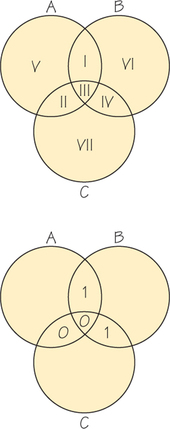
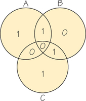
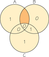
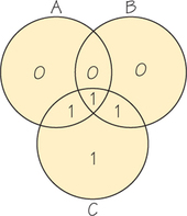
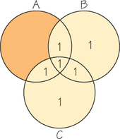
Assume that we want to send the message 1001. We append extra information to this message with the aid of the diagram in Figure 17.1. Begin by placing the four message digits in the four overlapping regions I, II, III, and IV, with the digit in the first position (starting at the left of the sequence) in region I, the digit in the second position in region II, and so on. For regions V, VI, and VII, assign 0 or 1 so that the total number of 1s in each circle is even (see Figure 17.2). The encoded message 1001101 is obtained by reading the entries in regions I through VII in order.
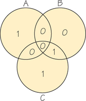
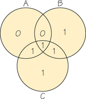
Using the diagram, we have encoded our message 1001 as 1001101. Now suppose that this encoded message is received as 0001101 (an error in the first position). How would we know an error was made? We place each digit from the received message in its appropriate region, as in Figure 17.3.
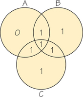
Noting that there is an odd number of 1s in both circles A and B, we instantly realize that something is wrong because the intended message had an even number of 1s in each circle. How do we correct the error? The answer involve; parity. (Parity refers to the oddness or evenness of a number; even integers have even parity and odd integers have odd parity.) Because circles A and B have the wrong parity and C does not, the error is located in the portion of the diagram ir circles A and B, but not in circle C, that is, region I (shaded in Figure 17.4). Here we also see the advantage of using only 0s and 1s to encode data. If you have onh two possibilities and one of them is incorrect, then the other one must be correct Because the 0 in region I is incorrect, we know that 1 is correct.
The Ubiquitous Reed-Solomon Codes 17.1
17.1
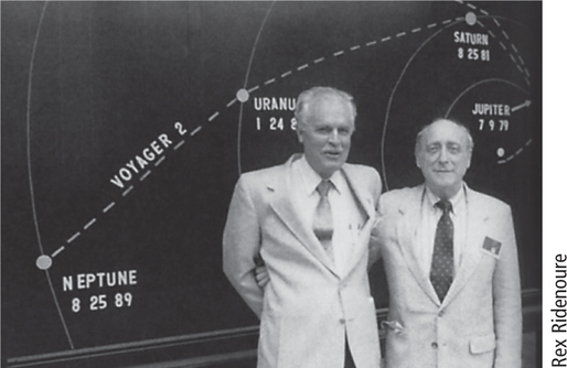
One of the mathematical ideas underlying current error- correcting techniques for everything from computer hard-disk drives to CD and DVD players was introduced in 1960 by Irving Reed and Gustave Solomon. Reed- Solomon codes made possible the stunning pictures of the outer planets sent back by the space probes Voyager 1 and Voyager 2. They make it possible to scratch a CD or a DVD and still enjoy the content.
“When you talk about CD players, digital television, and various other digital systems—all of those Reed-Solomon [codes] are an integral part of the system,” says Robert McEliece, a coding theorist at Caltech.
Why? Because digital information consists of 0s and 1s, and a physical device may confuse the two occasionally. Voyager 2, for example, was transmitting data at incredibly low power over billions of miles. Error-correcting codes are a kind of safety net, mathematical insurance against the vagaries of an imperfect material world.
In 1960, the theory of error-correcting codes was only about a decade old. Through the 1950s, a number of researchers began experimenting with a variety of error-correcting codes. But the Reed-Solomon paper, McEliece says, “hit the jackpot.” “In hindsight, it seems obvious,” Reed later said. However, he added, “Coding theory was not a subject when we published the paper.” The two authors knew they had a nice result; they didn’t know what impact the paper would have.
Five decades later, the impact is clear. The vast array of applications has settled the questions of the practicality and significance of Reed-Solomon codes. Billions of dollars in modern technology depend on ideas that stem from Reed and Solomon’s original work.
Source: Information from the article “The Ubiquitous Reed- Solomon codes” by Barry Cipra from SIAM News, January 1993, p. 1.
EXAMPLE 2![]() Error Correction
Error Correction
For practice, we will do another example. Consider the message 0111. Proceeding as before, we place 0 in region I and 1s in regions II, III, and IV. For regions V, VI, VII, we assign 0 or 1 so that the total number of 1s in each circle is even (see Figure 17.5). Then the message 0111 is encoded as 0111001. If this code word is received as, say, 0111011 (error in the sixth position), the diagram for the received word is shown in Figure 17.6. Then circle B has an odd number of 1s, and circles A and C have an even number. If the received message has only one error, then the error must be in circle B but not circles A and C. This tells us that the entry is region VI is incorrect. So, the error can be corrected.
Self Check 1
Use the circle diagram shown in Figure 17.1 to encode the message 0101.
- 0101110
Because the circle diagram method was designed to correct a received message with exactly one error, if a received message has two or more errors, the diagram method will never yield the correct message. For example, if the encoded message 0111001 is received as 1111011 (errors in positions 1 and 6), then only circle A has an odd number of 1s (see Figure 17.7), so our decoding method assumes that there is an error in a region in circle A but not in regions in circles B and C. Thus, our method incorrectly assumes that a single error occurred in region V (shaded in Figure 17.8).
The diagram technique can be used to encode all 16 possible binary messages of length 4, as shown in Table 17.1. The encoded messages are called code words. The three digits appended to each string of length 4 provide the “extra information” that is sufficient to infer the intended four-digit message, so long as the received seven-digit message has at most one error.
| Message | → | Code Word | Message | → | Code Word |
|---|---|---|---|---|---|
| 0000 | → | 0000000 | 0110 | → | 0110010 |
| 0001 | → | 0001011 | 0101 | → | 0101110 |
| 0010 | → | 0010111 | 0011 | → | 0011100 |
| 0100 | → | 0100101 | 1110 | → | 1110100 |
| 1000 | → | 1000110 | 1101 | → | 1101000 |
| 1100 | → | 1100011 | 1011 | → | 1011010 |
| 1010 | → | 1010001 | 0111 | → | 0111001 |
| 1001 | → | 1001101 | 1111 | → | 1111111 |
Because the diagram method can be used to encode only four-digit binary messages, it is not practical. We use it merely to illustrate a simple way to encode and decode messages. In the next section, we explain a method that can be used in more general settings.