Chapter 14. Structure of Solids
Objectives
- Understand the relationship between lattice vectors, unit cells, and crystal structures.
- Be able to identify each of the five two-dimensional Bravais lattices.
- Be able to determine the most efficient packing of atoms in metals.
- Given a three-dimensional model of an ionic crystal structure and a table of ionic radii, be able to (i) calculate the empirical formula, (ii) recognize the coordination number(s) of the atoms/ions, (iii) estimate the length of the unit cell edge, and (iv) calculate its density.
Logistics
- Students will work in pairs (one group of 3 if there is an odd number in the class).
- All students will complete Part A first.
- Parts B and C may be completed in either order. Your TA will assign half of the groups to work on A, then B, then C. The other half will work on A, then C, then B.
- All sections will be completed on the handouts in this lab, and these sheets (the last few pages of this lab) will be turned in to your TA before you leave the laboratory.
- Goggles do not need to be worn UNLESS someone in the class is working on a previous lab in which chemicals are being used.
Discussion
Unlike molecular substances, the strong bonding interactions in ionic and metallic substances are not confined to a discrete group of atoms (molecules). Rather, these substances form extended networks of atoms, which more often than not lead to the formation of crystals. This lab examines the structures of extended solids by considering some of the more common and symmetric crystal structures of metallic and ionic solids.
Part A: Translational Symmetry and Unit Cells in Two Dimensions
Structures of molecules are defined by the positions of all atoms that make up the molecule. It would be problematic to describe an extended solid in the same manner. First of all, there would be a huge number of atoms to consider, and secondly, the number of atoms in the crystal varies depending upon the macroscopic size of the crystal. Fortunately, there is a simpler way to describe the structures of extended solids. In all crystals there is a unit that contains a unique arrangement of atoms. Crystals are built up by repeating that unit over and over again in all three directions. This is similar to the way a wall is constructed by stacking identical bricks together. The repeating unit (or brick) is called a unit cell. The geometrical pattern of points on which the unit cells are arranged is called a lattice. Two things define the structure of an extended solid: 1) the dimensions and symmetry of the unit cell, and 2) the locations of atoms within the unit cell.
Before considering three-dimensional lattices it is useful to consider two-dimensional lattices, because they are simpler to describe and visualize. Figure 13.1 shows a two-dimensional array of lattice points. All lattice points have an identical environment. That is to say that if you sat on a lattice point and looked out at your surroundings the view would be identical, regardless of which lattice point you were on or how far you could see. In Figure 13.1 the lattice points are denoted by small circles. Their positions are defined by the lattice vectors, a and b. Beginning from any lattice point it is possible to move to any other lattice point through translation of an integer number of the two lattice vectors. This property, called translational symmetry, is the defining characteristic of a crystal. The parallelogram formed by the lattice vectors (shaded green in Figure 13.1) defines the unit cell. In two dimensions the unit cell is always some type of parallelogram defined by the lattice vectors, although it could be a special type of parallelogram, like a square. In two dimensions the unit cells can be tiled so that they completely cover the entire area of the lattice, with no gaps. In three dimensions the unit cells are parallelepipeds that can be stacked together to fill all space.
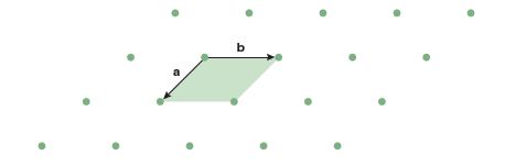
You might think that unit cells could adopt any number of different shapes. However, in two dimensions there are only five unique lattices. The lattice shown in Figure 13.1 is the most general case. The lattice vectors a and b are of different lengths and the angle between the two vectors, γ, is arbitrary. This lattice is called an oblique lattice. In Part A of the laboratory exercises you will determine the other four lattices that exist in two dimensions.
Lab Activity for Part A: Translational Symmetry
Materials: Each student will need a stencil. Complete these activities on the report pages.
- Let’s begin by determining what shapes can be used to tile space. Try to tile space with
each of the following shapes using the stencils provided. You are free to translate the
polygons as needed to cover space, but do not rotate the polygons. Shade in any areas
that are not covered by the tiling.
- Equilateral triangle (#4 on stencil)
- Square (#3 on stencil)
- Rectangle (#30 on stencil)
- Rhombus (#32 on stencil)
- Regular pentagon (#2 on stencil)
- Regular hexagon (#5 on stencil)
- Regular octagon (#13 on stencil)
- Do you think there are other shapes not listed above that would tile space? If so, identify those shapes and make a drawing to demonstrate your assertion.
- A lattice is defined by a collection of points connected by the lattice vectors. In two dimensions, there are two lattice vectors, a and b, which form a unit cell that must be a parallelogram. To generate a 2-D lattice for each of the shapes that tile all space (found in step 1) place a point at the center of each polygon. Next, draw the lattice vectors a and b by connecting the points, and shade the parallelogram that is the unit cell. In some cases the unit cell will have the same shape as the polygon used to tile space, while in other cases it will be a different shape.
- Previously we learned that an oblique cell has lattice vectors, a and b, that are not equal to each other and there is an arbitrary angle, γ, between them. This is the unit cell for one of the five two-dimensional unit cells. Based on your results from steps 1 and 2, determine the relationships between the lattice vectors for the four additional two-dimensional lattices and use this information to complete the table found on the Report Sheet.
Part B: Close Packing and the Structures of Metallic Solids
In this section we are going to take a closer look at the structures of metallic solids. Metallic bonding tends to favor crystal structures where the atoms are packed together closely, so to understand the structures of metals we begin by considering the most efficient way to pack spheres together. If we approximate the atom as a sphere and construct a close-packed layer of spheres each atom would have six neighbors as shown by the large grey spheres in Figure 13.2a.
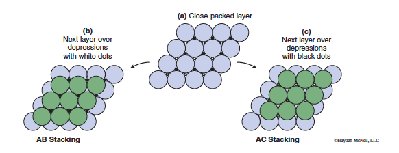
To form a three-dimensional structure the next step would be to stack layers together. The spheres will be most closely packed if the next layer of spheres sits in the depressions marked with either the white or black dots in Figure 13.2a. It’s important to note that the spheres in a single layer are too large to sit over both sets of depressions.
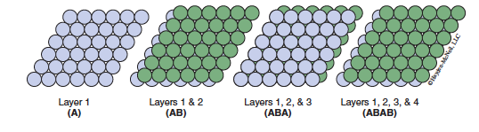
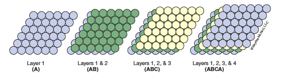
If we only have two layers then it doesn’t matter which of the two types of stacking we choose. They are indistinguishable. However, when we stack a large number of layers together to form a three-dimensional crystal the stacking pattern makes a difference. There are many different ways you might imagine stacking close-packed layers of spheres. Fortunately, the structures of many metals can be described by two simple stacking sequences. Those two sequences are shown in Figures 13.3 and 13.4.
If the third layer lies directly over the positions where the spheres in the first layer sit, and the fourth layer lies directly over the positions where the spheres in the second layer sit, the stacking pattern repeats every other layer and is designated as ABAB… stacking. This type of stacking leads to a 3-D structure called hexagonal close packing (hcp) (Figure 13.3).
If the third layer is offset in such a way that it lies over the green dots in Figure 13.3 it will not sit directly above either layers 1 or 2. The three-layer sequence repeats beginning with the fourth layer (which lies directly over the spheres in the first layer) to give an ABCABC… stacking pattern. This type of structure is called cubic close packing (ccp) (shown in Figure 13.4).
Lab Activity for Part B: Close Packing and the Structures of Metallic Solids
Materials: Each group will need a solid state model kit and ruler. This kit contains a basewith metal rods and a bag of clear spheres. The spheres fit onto the metal rods. Do not tipthe base to get the spheres off, as the metal rods will fall out too. A ruler may be found onyour stencil. Complete these activities on the report pages.
- To build up the structure of a hypothetical 2-D metallic solid we want to pack spheres into a single layer as tightly as possible, as shown for circles in Figure 13.2a. Using a solid state model kit, slide 9 clear spheres onto the metal rods to reproduce the 2-D packing of spheres seen in Figure 13.2a. How many neighbors does the sphere in the center touch? This is the coordination number; record it on your Report Sheet. (If the layer extended infinitely all spheres would have the same coordination number as the sphere in the center.)
- For the structures of real metals we must move to three dimensions by adding additional layers. Before moving on have your TA check that the layer of spheres from the previous step is correctly placed on the rods.
- To construct a primitive hexagonal packing arrangement, repeat this pattern from the previous step by stacking two identical layers directly on top of the bottom layer—use 9 spheres for each layer. If done correctly this should result in an AAA packing. Use a ruler to measure the height from the top of the model base to the top of the spheres on the top (3rd) layer. Record this value on your Report Sheet.
- How many nearest neighbors does each atom have (i.e., how many neighboring spheres does each sphere touch)? Record this coordination number on your Report Sheet.
- Remove the third and second layers of spheres, leaving the first layer in place. Now add nine spheres to form a second layer that sits in a set of depressions created by the first layer. (See Figure 13.3 for guidance.) Finally, place a third layer that lies directly over the spheres in layer one to form ABA stacking. Use a ruler to measure the height from the top of the model base to the top of the spheres on the top (3rd) layer. Record this value on your Report Sheet.
- How many nearest neighbors does each atom have (i.e., how many neighboring spheres does each sphere touch)? Record this coordination number on your Report Sheet.
- Remove the third layer of spheres from the model, leaving the first and second layers in place. Now add a new third layer so that the spheres sit in a set of depressions created by the second layer and they are not directly over the first layer. (See Figure 13.4 for guidance.) This will form ABC stacking. Use a ruler to measure the height from the top of the model base to the top of the spheres on the top (3rd) layer. Record this value on your Report Sheet.
- How many nearest neighbors does each atom have (i.e., how many neighboring spheres does each sphere touch)? Record this coordination number on your Report Sheet.
- Looking at your heights from steps 6, 8, and 10, which arrangement(s) has the largest height? Which has the smallest height?
- Looking at the coordination numbers (CN) from steps 7, 9, and 11, which arrangement(s) has the largest coordination number? Which has the smallest?
- Using the measured heights and coordination numbers as a reference, which arrangement(s) do you think has the most efficient packing?
Part C: The Structures of Ionic Solids
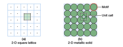
The crystal structures of ionic compounds tend to be a little more complicated than those of close-packed metals. Because not all of the atoms are the same we will need at least two atoms per lattice point, and sometimes many more. Let’s begin in two dimensions to illustrate how this works in practice. Consider a 2-D square lattice as shown in Figure 13.5a. If we put a single atom on each lattice point we would have a 2-D crystal structure, as shown in Figure 13.5b.
If we were to keep the same structure but replace the single atoms with equal numbers of anions and cations we could obtain a variety of 2-D ionic structures. The most energetically favorable way to make the replacement would be to choose a structure where there are no cation−cation or anion−anion contacts—such a structure is shown in Figure 13.6a. What is the unit cell of this 2-D ionic crystal? You might think that we can use the same unit cell (labeled “Unit cell 1” in Figure 13.6b), however, this is not a valid unit cell because not all of the corners of the unit cell fall on the same type of atom. This means that not all lattice points are identical, which is not allowed.
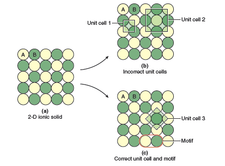
Your next instinct might be to double the size of your square unit cell (labeled “Unit cell 2” in Figure 13.6b). This is a better choice because if we tile this unit cell we see that all of the unit cells contain the same pattern of atoms: yellow atoms at the corners and center of the unit cell, and green atoms at the midpoint of each edge of the unit cell. However, this unit cell is also incorrect because it is not the smallest unit cell that we can choose. The correct unit cell is shown in Figure 13.6c (labeled “Unit cell 3”). We see that it is also a square that tiles all space with identical contents, but it is smaller than unit cell 2. We always choose the smallest possible unit cell; unit cells that have the same shapebut are unnecessarily large are incorrect. In this example the correct unit cell contains 4 × ¼ = 1 yellow atom and 1 green atom, corresponding to an empirical formula of AB. We can also see that the structure is built by placing the 2 atom motif circled in Figure 13.6c on each point of the square lattice.
- The unit cells must tile (stack) together to cover all space (volume) and the positions and type of each atom must be identical in all unit cells.
- If you can draw multiple unit cells that satisfy the above criterion, the correct unit cell is the one that has the highest symmetry (rectangular is more symmetric than oblique, square and hexagonal are more symmetric than rectangular) and the smallest volume.
- If you can find any point in the structure where you can rotate by 90° and get a structure that looks identical the lattice must be a square lattice.
- If you can find any point in the structure where you can rotate by 120° and get a structure that looks identical the lattice must be a hexagonal lattice.
- If neither of the above rotations exist but you can draw a line through the structure that splits it into mirror images, or rotate by 180° and get an identical structure, the lattice must be a rectangular lattice.
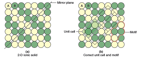
Before moving on to three-dimensional ionic structures, let’s do one more 2-D example, this one a bit more complicated. Consider the pattern of atoms shown in Figure 13.7a. In this structure we have zigzag stripes of the two different types of atoms, A and B. Presented with this structure the unit cell may not be immediately obvious to you. Following the checklist above we look for 90° or 120° rotations that produce an identical structure, but there are none to be found. However, we can draw diagonal lines from the lower left to the upper right that split the structure into mirror images (as shown by the black dashed line in Figure 13.7a). This tells us that we are looking for a rectangular unit cell. After some trial and error you should be able to find the shaded unit cell shown in Figure 13.7b. Just to show that all unit cells are identical the faint dotted lines show three neighboring unit cells. So this structure possesses a primitive rectangular lattice with a motif that contains 2 yellow atoms and 2 green atoms, giving an empirical formula of AB.
After trying your hand at identifying the unit cells, motifs, and lattices of some 2-D patterns of atoms, you will move on to 3-D models of real ionic crystals. For this lab we will limit our discussions to ionic compounds with cubic unit cells. Some of the more common cubic crystal structures of ionic compounds are shown in Figure 13.8. Note the coordination numbers (number of nearest neighbors) and coordination geometries (shape formed by the nearest neighbors) for each. Notice how the number of anions surrounding the cation decreases from eight in the cesium chloride (CsCl) structure (cubic coordination geometry), to six in the rock salt (NaCl) structure (octahedral coordination geometry), to four in the zinc blende (ZnS) structure (tetrahedral coordination geometry).
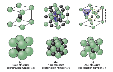
The CsCl structure can be derived from a primitive cubic arrangement of anions by filling the cubic hole that sits at the middle of the unit cell with a cation (Figure 13.8a). The NaCl and ZnS structures both contain a cubic close-packed anion arrangement. In NaCl the cations fit into what are called octahedral holes; these are void spaces in the structure that are surrounded by six anions in the shape of an octahedron. The octahedral holes are located on the edges and in the center of the unit cell. In the NaCl structure all of the octahedral holes are filled with cations (Figure 13.8b).
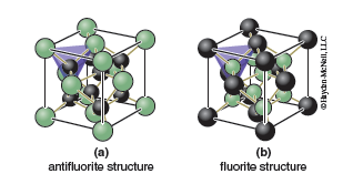
A close-packed array of anions also contains what are called tetrahedral holes, void spaces that are surrounded by four anions in the shape of a tetrahedron. The easiest way to see the tetrahedral holes is to divide the unit cell up into 8 smaller cubes of equal size, one for each quadrant. The tetrahedral holes are located at the center of each of these smaller cubes. If we fill half of the tetrahedral holes with cations the zinc blende structure results. It is also possible to fill all of the tetrahedral holes, in which case the structure that results is called the antifluorite structure, which is shown in Figure 13.9a. There are relatively few examples of compounds with the antifluorite structure, Na2O being one example. If we reverse the positions of the anions and cations the fluorite structure (Figure 13.9b) is obtained. This arrangement, which has a close-packed array of cations with anions filling the tetrahedral holes, is somewhat more common. Perhaps the best known example is the mineral fluorite, CaF2. If only one-half of the tetrahedral holes are filled we can obtain the zinc blende (ZnS) structure shown in Figure 13.8c.
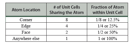
It is often necessary to know how many atoms are in the unit cell. Looking at the CsCl structure, Figure 13.8a, one might conclude that there are 9 atoms per unit cell. That counting neglects the fact that the atoms which reside on a boundary (corner, edge, face) of a unit cell are shared by more than one unit cell. Hence only a fraction of the atom truly resides in the unit cell. Atoms that reside on the corner of a unit cell are shared by eight unit cells so that only ⅛ of each corner atom is actually within the unit cell. Atoms that reside on an edge of the unit cell are shared by four unit cells so that ¼ of the atom is in each unit cell. Atoms that reside on a face of the unit cell are shared by two unit cells so that ½ of the atom is in each unit cell. These special positions are shown in Table 13.1. You will need to consider this when determining how many cations and anions are in your unit cell when completing the Part C activities.
Table 13.1 The fraction of an atom sitting on the unit cell boundary that resides within the unit cell.1
To complete the final part of this lab you will answer a series of questions by examining a pre-constructed model of an ionic crystal. Each student in the class will be assigned a different compound. Your TA will give you the name of your compound (i.e., scandium nitride) and you will use the pre-constructed model type A. The models represent one in the subset of the structure types discussed here (zinc blende, sodium chloride, cesium chloride, fluorite, and antifluorite). The cations are represented by the colored spheres (green or blue), and the anions are represented by the clear spheres. The approach needed to complete the analysis of your ionic compound is outlined below.
- Structure type: Look at the appropriate 3-D model of your compound and match it to one of the structures shown in Figure 13.8 or 13.9.
- Number of cations in unit cell: Determine the number of cations (colored spheres) in the unit cell. For atoms sitting on a corner, edge, or face of the unit cell, only count the fraction inside the unit cell (see Table 13.1).
- Number of anions in unit cell: Determine the number of anions (clear spheres) in the unit cell. For atoms sitting on a corner, edge, or face of the unit cell, only count the fraction inside the unit cell (see Table 13.1).
- Empirical formula: The ratio can be determined from the number of each type of ion in the unit cell, reduced to the smallest ratio (e.g., 4 Ca and 8 F in the unit cell would have CaF2 as the empirical formula).
- Equation for the length of the unit cell edge: Determine the path along which the cations and anions touch (only consider cation−anion contacts; in ionic structures ions of the same type do not touch, even though they may appear to touch in the models), and add up the radii to obtain an equation that gives the length of an edge, a face diagonal, or a body diagonal of the unit cell in terms of the radii of the ions. Once you have an expression for the length of the path along which the ions touch, you may need to use geometry to get the length of the edge of the cube. The following mathematical relationships may be useful: (a) the face diagonal is √2 times longer than an edge, and (b) the body diagonal is √3 times longer than an edge.
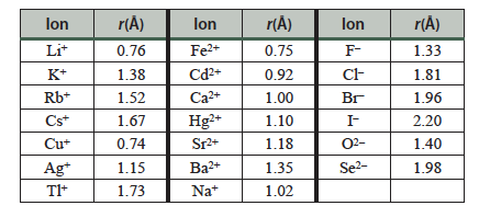
- Estimate the length of the unit cell edge: Use the equation developed above and the following table of ionic radii to estimate the length of your unit cell in Å.
- Estimate the density: Density is an intensive property so the density of one unit cell and the density of a crystal you can hold in your hand will be the same. If we add up the masses of all of the atoms in the unit cell and divide by the volume of the unit cell (the volume of a cube is a3 where a is the length of an edge) we can estimate the density. Be sure to use appropriate units (mass in grams, volume in cm3).
Table 13.2 Ionic radii of several cations and anions.
1 It is only the position of the center of the atom that matters. Atoms that reside near the boundary of the unit cell, but not on a corner, edge, or face, are counted as residing 100% within the unit cell.
Lab Activity for Part C: The Structures of Ionic Solids
Materials: Each group will receive an unknown 2-D ionic structure (on paper) from theirTA; this will be used in step 15. Each row of the lab will have 3-D ionic models, A, B and C.These will be used to complete step 16. Each group of students will use model A to completestep 17.
- Obtain an unknown sheet from your TA. Each sheet contains two separate 2-D ionic structures. For each structure sketch the unit cell, circle the motif, determine the number of each type of atom in the unit cell, and the empirical formula. Use the tips on slide 8 to guide you. Enter that information directly on your unknown sheet. Turn this in with your Report Sheet before leaving lab.
- For the next several questions you will examine pre-constructed models of ionic crystals. Looking at models A, B, and C, determine the structure-type of each model. Use Figures 13.8 and 13.9 to assign each unknown structure a type: cesium chloride (Figure 13.8a), rock salt (Figure 13.8b), zinc blende (Figure 13.8c), antifluorite (Figure 13.9a) or fluorite (Figure 13.9b).
- Obtain the formula name of your assigned ionic compound from your TA (e.g., scandium nitride). Use solid-state model A to answer the following questions on your Report Sheet. Use the tips on slide 8 to guide you.
- There are two unit cells stacked vertically in this model. How many anions (clear spheres) are in the unit cell? How many cations (colored spheres) are in the unit cell?
- What is the empirical formula (i.e., Al2O3) of your unknown?
- What is the coordination number and geometry (cubic, octahedral, tetrahedral) of the cation?
- What is the coordination number and geometry (cubic, octahedral, tetrahedral) of the anion?
- Derive an equation for the length of the unit cell edge, a, in terms of the ionic radii of the cation and anion, r(cation) and r(anion). Use the information on slide 8 to guide you. Remember that in ionic compounds it is the anions and cations that touch (anions do not touch each other, nor do cations touch each other).
- Estimate the length of the unit cell edge, a, for your solid. Use the ionic radii in Table 13.2 for assistance in this calculation.
- Using the estimated length of the unit cell edge, a, and the number of atoms in the unit cell, calculate the density for your solid. Consult the CRC Handbook of Chemistry and Physics to check the accuracy of your answer. (Note: Your value may not exactly match the CRC Handbook value, but it should be close.)