image
FIGURE 18-21 Kinesin-1 uses ATP to “walk” down a microtubule. (a) In this diagram, the two kinesin heads are shown with differently colored linker domains (yellow and red) to distinguish them. The cycle is shown starting after kinesin has taken a step, with the leading head tightly bound to the microtubule and not bound by any nucleotide, while the trailing head is weakly bound to the microtubule and has ADP bound. The leading head then binds ATP (step 1), which induces a conformational change that causes the yellow linker region to swing forward and dock into its associated head domain, thereby thrusting the trailing head forward (step 2). The new leading head now finds a binding site 16 nm down the microtubule, to which it binds weakly (step 3). The leading head now releases ADP and binds tightly to the microtubule, which induces the trailing head to hydrolyze ATP to ADP and Pi (step 4). Pi is released and the trailing head is converted into a weak binding state, and also releases the docked linker domain. The cycle now repeats itself for another step. See R. D. Vale and R. A. Milligan, 2000, Science 288:88. (b) Structural model of two kinesin heads (purple) bound to a protofilament in a microtubule. The trailing head, at left, has bound ATP and has thrust the other head into the leading position. Notice how the linker domain (yellow) is docked into the trailing head, whereas the linker domain (red) of the leading head is still free.
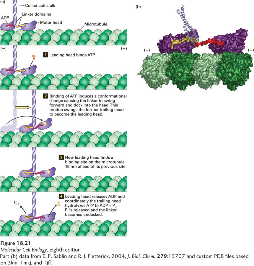
[Part (b) data from E. P. Sablin and R. J. Fletterick, 2004, J. Biol. Chem. 279:15707 and custom PDB files based on 3kin, 1mkj, and 1jff.]