Deconvolution and Confocal Microscopy Enhance Visualization of Three-Dimensional Fluorescent Objects
[Courtesy of James Evans, PhenoVista Biosciences.]
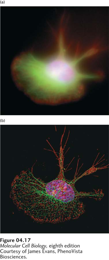
EXPERIMENTAL FIGURE 4-17Deconvolution fluorescence microscopy yields high-resolution optical sections that can be reconstructed to create one three-dimensional image. A macrophage cell was stained with fluorochrome-labeled reagents specific for DNA (blue), microtubules (green), and actin microfilaments (red). The series of fluorescent images obtained at consecutive focal planes (optical sections) through the cell were recombined in three dimensions. (a) In this three-dimensional reconstruction of the raw images, the DNA, microtubules, and actin appear as diffuse zones in the cell. (b) After application of the deconvolution algorithm to the images, the fibrillar organization of microtubules and the localization of actin to adhesions are readily visible in the reconstruction.
[Courtesy of James Evans, PhenoVista Biosciences.]
Conventional fluorescence microscopy has two major limitations. First, the fluorescent light emitted by a sample comes not only from the plane of focus, but also from molecules above and below it; thus the observer sees a blurred image caused by the superposition of fluorescent images from molecules at many depths in the cell. The blurring effect makes it difficult to determine the actual spatial arrangements. Second, to visualize thick specimens, consecutive (serial) images at various depths throughout the sample must be collected and then aligned to reconstruct structures in the original thick tissue. Two general approaches have been developed to obtain high-resolution three-dimensional information. Both of these methods require that the image be collected electronically so that it can then be computationally manipulated as necessary.
The first approach, called deconvolution microscopy, uses computational methods to remove fluorescence contributed by out-of-focus parts of the sample. Consider a three-dimensional sample in which images from three different focal planes are recorded. Since the whole sample is illuminated, the image from plane 2 will contain out-of-focus fluorescence from planes 1 and 3. If we knew exactly how out-of-focus fluorescence from planes 1 and 3 contributed to the light collected in plane 2, we could computationally remove it. To obtain this information for a particular microscope, we can make a series of images of focal planes from a test slide containing tiny fluorescent beads. Each bead represents a pinpoint of light that becomes a blurred object outside its focal plane; from these images we can determine a point spread function that enables us to calculate the distribution of fluorescent point sources that contributed to the “blur” when out of focus. Once we have calibrated the microscope in this manner, the experimental series of images can be computationally deconvolved. Microscopes with automated stages to collect the images, and associated software programs to deconvolve the images, are available commercially. Images restored by deconvolution display impressive detail without any blurring, as illustrated in Figure 4-17.
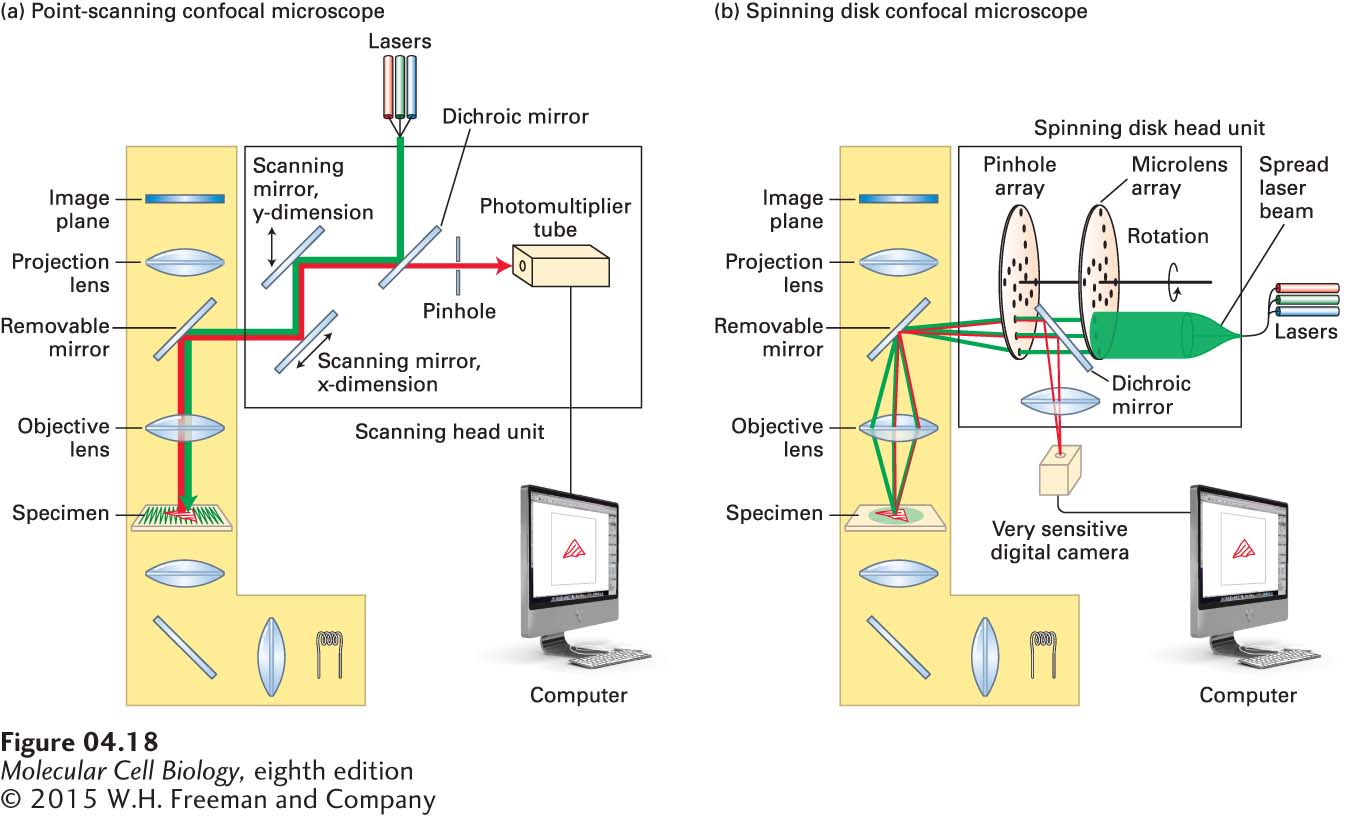
The second approach to obtaining better three-dimensional information is called confocal microscopy because it uses optical methods to obtain images from a specific focal plane and exclude light from other planes. Confocal microscopes collect a series of images focused through the vertical depth of the sample, from which an accurate three-dimensional representation can be computationally generated. Two types of confocal microscopes are in common use today, a point-scanning confocal microscope (also known as a laser-scanning confocal microscope, or LSCM) and a spinning disk confocal microscope. The idea behind each microscope is to both illuminate and collect emitted fluorescent light from just one small area of a focal plane at a time in such a way that out-of-focus light is excluded. This can be achieved by collecting the emitted light through a pinhole before it reaches the detector—light from the illuminated focal plane passes through, whereas light from other focal planes is largely excluded. The illuminated area is then moved across the whole focal plane to build up the image electronically. The two types of microscopes differ in how they cover the image. The point-scanning microscope uses a point laser light source at the excitation wavelength to rapidly scan the focal plane in a raster pattern, collects the emitted fluorescence in a photomultiplier tube, and thereby builds up an image (Figure 4-18a). It can then take a series of images at different depths in the sample to generate a three-dimensional reconstruction. A point-scanning confocal microscope can provide exceptionally high-resolution images in both two and three dimensions (Figure 4-19), although it has two minor limitations. First, it can take significant time to scan each focal plane, so if a very dynamic process is being imaged, the microscope may not be able to collect images fast enough to follow the dynamics. Second, it illuminates each spot with intense laser light, which can bleach the fluorochrome being imaged and damage live cells by phototoxicity, thereby limiting the number of images that can be collected.
FIGURE 4-18Light paths for two types of confocal microscopy. Both types of microscopy are assembled around a conventional fluorescence microscope (yellow shading). (a) Light path in a point-scanning confocal microscope. A single-wavelength point of light from an appropriate laser is reflected off a dichroic mirror and bounces off two scanning mirrors and from there passes through the objective lens to illuminate a spot in the specimen. The scanning mirrors rock back and forth in such a way that the light scans the specimen in a raster fashion (see green lines in the specimen). The fluorescence emitted by the specimen passes back through the objective lens and is bounced off the scanning mirrors onto the dichroic mirror. This allows the light to pass through toward the pinhole. This pinhole excludes light from out-of-focus focal planes, so the light reaching the photomultiplier tube comes almost exclusively from the illuminated spot in the focal plane. A computer then takes these signals and reconstructs the image. (b) Light path in a spinning disk confocal microscope. Here, instead of using two scanning mirrors, the beam from the laser is spread to illuminate pinholes on the coupled spinning disks, the first consisting of microlenses to focus the light on pinholes in the second disk. The excitation light passes through the objective lens to provide point illumination of a number of spots in the specimen. The fluorescence emitted passes back through the objective lens and through the holes in the spinning disk, and is then bounced off a dichroic mirror into a sensitive digital camera. The pinholes in the disk are arranged so that as it spins, it rapidly illuminates all parts of the specimen several times. As the disk spins as fast as 3000 rpm, very dynamic events in live cells can be recorded.
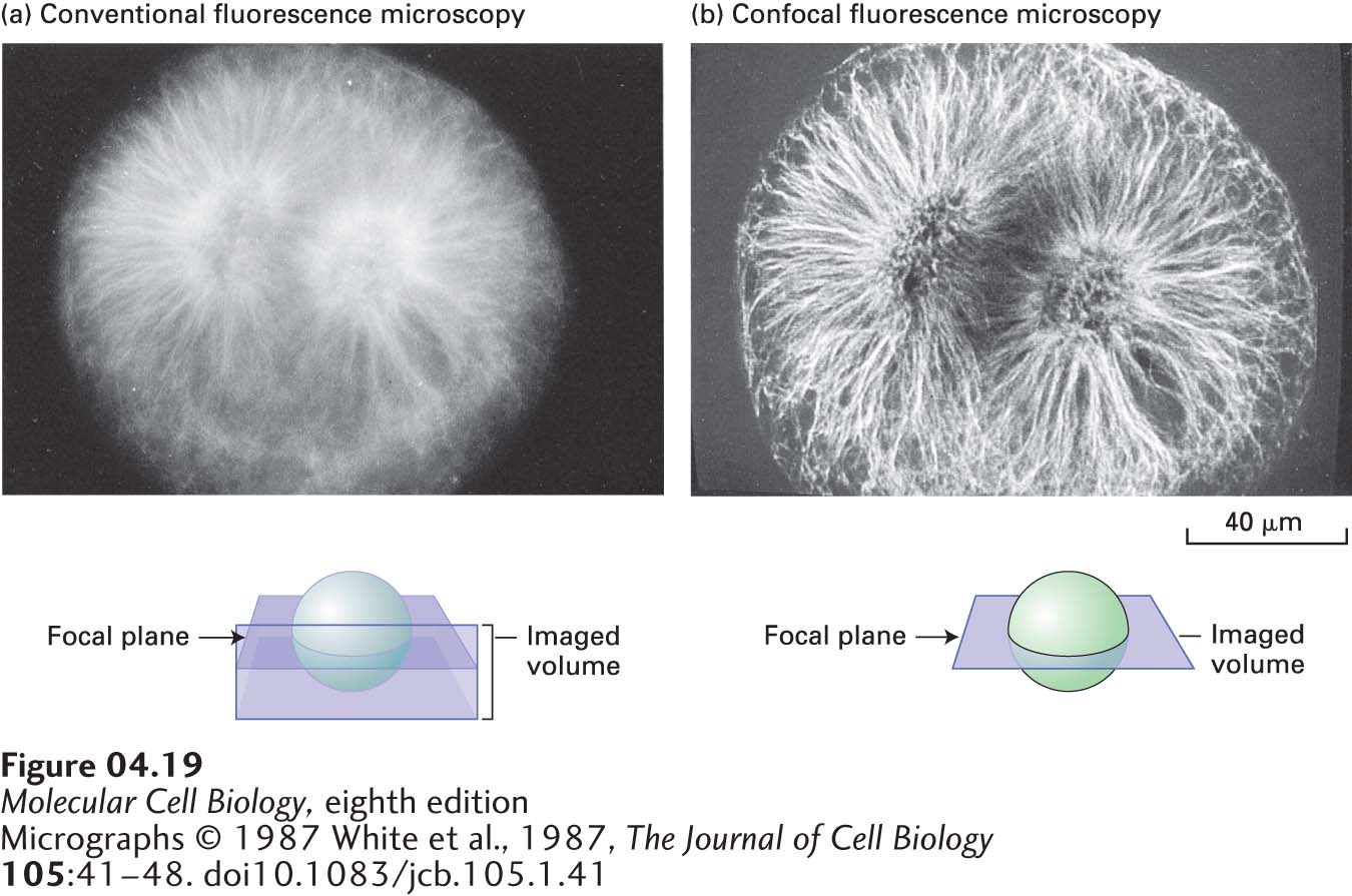
FIGURE 4-19Confocal microscopy produces an in-focus optical section through thick cells. A mitotic fertilized egg from a sea urchin (Psammechinus) was lysed with a detergent, exposed to an tubulin antibody, and then exposed to a fluorescein-tagged antibody that binds to the anti-tubulin antibody. (a) When viewed by conventional fluorescence microscopy, the mitotic spindle is blurred. This blurring occurs because background fluorescence is detected from tubulin above and below the focal plane as depicted in the sketch. (b) The confocal microscopic image is sharp, particularly in the center of the mitotic spindle. In this case, fluorescence is detected only from molecules in the focal plane, generating a very thin optical section.
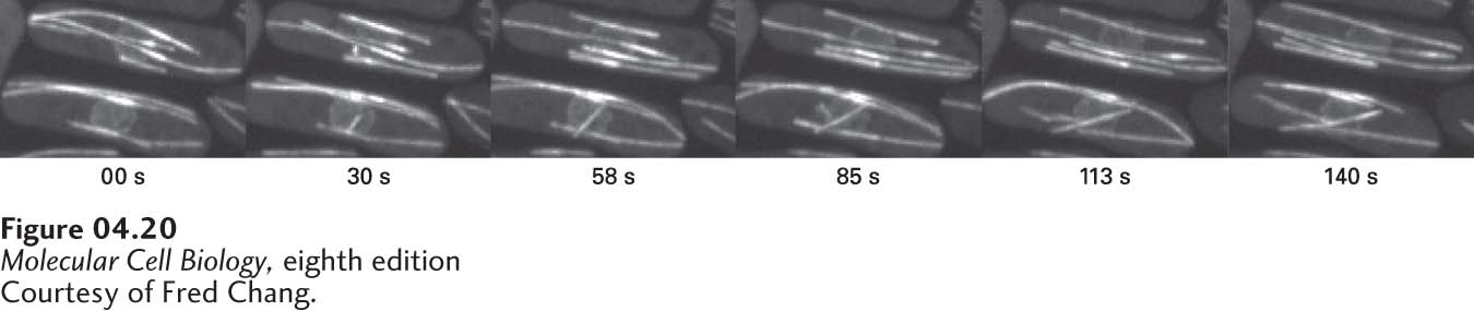
The spinning disk microscope circumvents these two problems (Figure 4-18b). The excitation light from a laser is spread out and illuminates a small part of a disk spinning at high speed; for example, at 3000 rpm. The disk in fact consists of two linked disks: one with 20,000 lenses that precisely focuses the laser light on 20,000 pinholes of the second disk. The pinholes are arranged in such a way that they completely scan the focal plane of the sample several times with each turn of the disk. The emitted fluorescent light returns through the pinholes of the second disk and is reflected by a dichroic mirror and focused onto a highly sensitive digital camera. In this way, the sample is scanned in less than a millisecond, so the real-time location of a fluorescent reporter can be captured even if it is highly dynamic (Figure 4-20). A current limitation of the spinning disk microscope is that the pinhole size is generally fixed and has to be matched to the magnification of the objective lens, so it is generally configured for use with a 63× or 100× objective and is less useful for the lower-magnification imaging that might be required in tissue sections. However, within the last year, spinning disk head units have become available in which the pinhole size can be changed. Thus the point-scanning and spinning disk confocal microscopes have overlapping and complementary strengths.
Page 149
[Courtesy of Fred Chang.]
EXPERIMENTAL FIGURE 4-20The dynamics of microtubules can be imaged on the spinning disk confocal microscope. Six frames from a movie of GFP-tubulin in two rod-shaped cells of fission yeast are shown.