Chapter 1. APPENDIX B SALI and Laboratory Tools
Introduction
Laboratory Equipment Assessment
Anyone can potentially be a beginner to an expert in the use of different pieces of lab equipment. To simplify categorizing one’s level of training with lab equipment, levels are assigned based on expertise. Level 0 on this scale means no experience and no skill; however, Level 1 is an indicator of some familiarity with a given tool. This skill level can be increased to the point where the full potential of the tools can be applied to problems that the user has never encountered before.
Level 1: Basic—Self-taught or peer taught essential knowledge
Level 2: Practiced—Essential lab skills and tools through practice in lab or the learning center
Level 3: Functional—Functional application of tool use strategy in lab activities
Level 4: Problem-Solver—Practical ability to use tools in different contexts and in independent projects
Tool Level Assessment: Students are expected to be at functional Level 3 with all lab tools by the time they need to use them during lab experiments. They will be assessed in lab, or in the learning center. We encourage everyone to be pre-assessed in the learning center so they achieve Level 3 for at least one tool set prior to the actual labs in which these tools are used.
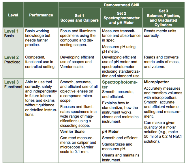
Table B.1 Strategic Approach to Learning Instrumentation Worksheet
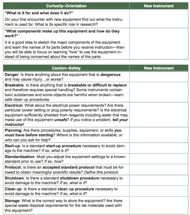
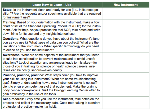
Introduction to Basic Instrumentation
On the following pages of this appendix, you will find some basic information for equipment that you will use throughout BIO 204 and 205.
1. Compound Microscope
Introduction to Microscopy
In the 1670s, Anton van Leeuwenhoek opened the door to an important world of biological investigation, using a small magnifying lens to view tiny microorganisms for the first time that were smaller than 1/10 of a millimeter. The most common magnifying tools in biology today are the compound light microscope and the stereoscopic dissecting scope. Modern compound light microscopes enable us to view objects as small as 0.1 micrometers (μm) or 100 nanometers (nm). Standard college microscopes use a three-lens system: two imaging lenses, the ocular and objective lenses, magnify the specimen; an illumination lens, the condenser lens, focuses and spreads light evenly across the specimen.
Using the Compound Light Microscope
The light microscope is widely used in biology and the health sciences. Learn to use and care for this tool correctly so that you will always get the clearest, optimal image allowed by the range of the scope, and avoid damage to this valuable instrument. Read this section carefully before you handle any microscope.
Purpose
To learn how to use the compound microscope effectively and safely
Materials
Specimen slides: letter “e” slide and different colored threads
Immersion oil
Windex and lens paper
Compound Microscope Procedure
- Plug in the scope, and turn on the light using the rotating switch on the base.
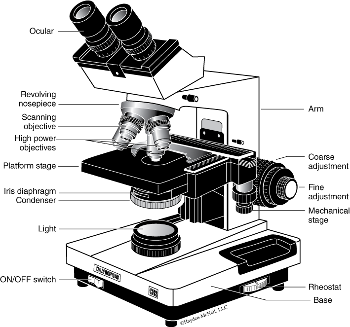
- Survey the parts of the microscope (Figure B.1). Notice the ocular lens on the main body tube of the microscope and 3 or 4 objective lenses on the rotating nosepiece below the body tube. The magnifying power of each objective lens is marked on the side of the lens tube. Microscope slides are mounted on the microscope stage. The condenser lens, below the stage, focuses light from the illumination system. To regulate the amount of light passing through the condenser lens, the iris diaphragm can be opened or closed using a small lever. The arm of the scope supports the body tube and objective lenses on the nosepiece and the stage; the base stabilizes the microscope.
- Position the low power or shortest objective lens over the specimen, in direct line with the ocular lens or eyepiece tube; the objective lens should “click” into proper position.
CAUTION!!
ALWAYS carry your microscope with two hands. The cord should be wrapped neatly around the cord holder. Hold the ARM and BASE of the scope, always above the waist, while carrying the microscope to your workspace.
NEVER use the coarse focus knob to focus when using a high power lens. Microscopes are commonly damaged when a high power objective lens breaks through a slide.
NEVER place or remove a slide when a high power lens is in use.
ALWAYS use the fine focus knob when focusing with a higher power objective.
ALWAYS use the 4× objective when first focusing on a slide and when placing or removing slides on the stage.
ALWAYS clean microscope lenses with lens paper.
Setting Up and Adjusting the Microscope
- Slide: Obtain letter “e” and colored thread slides from the side bench. Immersion oil, lens paper, and acid alcohol for cleaning the lenses are at your workstations.
- Objective: Make sure the stage is in its most downward position and the 4× objective lens is positioned directly above the opening in the stage. If not, use the coarse focus knob to move the stage and rotate the 4× objective into position until it “clicks” into place.
- Mounting the slide: Mount the letter “e” slide by opening the slide holding arm and placing the slide on the stage with the coverslip up. Move the slide on the stage using the stacked stage knobs (i.e., x-y travel knobs) below the stage on the left side of the scope. You will use these knobs to move your specimen while using the scope. Position the “e” directly above the stage opening.
- Illumination: Adjust the light using the brightness dial on the right side of the base. Always rotate this dial slowly to give the glowing filament time to warm up and cool down slowly; this will extend the life of the filament. Look into the eyepiece. You should see a round circle of light. Don’t worry if you cannot see the “e”; we will discuss focusing below.
- Focusing the condenser lens: Look under the stage just below the condenser lens, and find the diaphragm lever. While looking through the eyepiece, move the diaphragm to the left and right. Adjust the diaphragm so the light is even and diffuse.
- If the light appears uneven or looks like a series of halos (A), the condenser lens needs to be focused. Find the condenser focus knob on the right side of the scope just in front of the focus knobs. Focus the condenser up and down until the eld of view is evenly illuminated (B). The top of the condenser lens should be just below the stage opening approximately 1–2 mm away. Using too much light when viewing objects in the microscope often reduces rather than enhances resolution. However, you will have to increase the brightness when you use the higher power objective.
Image quality is generally improved with low, diffuse light.
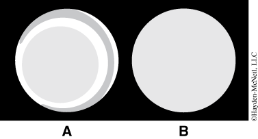
- Focusing: Center your specimen over the hole in the microscope stage. Always start with the lowest power objective lens. Observe the objective lens from the side as you raise the stage as close to the objective as possible; then look through the eyepiece.
- Locate the coarse and fine focus knobs; turn the coarse focus knob so the specimen moves away from the objective lens.
- Using the coarse focus knob, back the objective lens away from the slide.
- When you are able to see the “e,” focus the image as clearly as possible with the coarse focus knob, then use the fine focus knob to maximize image resolution.
- The two ocular lenses (binocular) have features designed to improve specimen image.
- The inter-pupillary distance spacing adjustment between the eyepieces enables you to match the distance between the ocular lenses to the distance between your eyes. This spacing is correct when you look through both oculars and see a single clear circle of light. Slide the eyepieces left or right until the double images merge into one.
- The left eyepiece diopter ring allows you to compensate for focusing differences between your left and right eyes. To use this feature, close your left eye and focus on the specimen with the fine focus knob using only your right eye; then close your right eye and use the diopter ring to obtain a clear image with your left eye only.
- Increasing resolution: Adjust the iris diaphragm by moving the lever from left to right. Is your image resolution constant, or does it get better or worse? If you have a blue light filter on your scope, observe your specimen with and without the filter. Is your resolution better or worse with the filter? (Remember to replace the filter when you are done.)
IMPORTANT! Use the coarse focus knob at low power only!
Focus by backing the objective lenses away from the slides!
Why do we insist that you always back the objective lens AWAY from the slide while using the coarse focus knob?
- Magnification: Magnification is calculated by multiplying the power of the ocular lens (in our scopes 10×) by the power of the objective lens.
- Higher Magnification: Go to the next higher power objective only after you have a well-focused image at low power. When the image is in sharp focus at low power, you can rotate the nosepiece to the next higher power objective lens.
- Image inversion and reversal: When viewing a specimen through a compound microscope, the image is reflected and inverted by the microscope lenses. This is known as “image inversion.”
- For each objective lens, note how much of the letter “e” is visible in the field of view.
- What details do you see as magnification increases?
- Observe the letter “e” with the microscope with the “e” right side up with the 4× objective. Rotate the 10× objective into place. Focus on the letter “e” using the fine focus—record your observations. Change to the 40× objective-record your observations.
- Compare the orientation of the letter on the microscope stage with the image under the scope. Does it look the same?
- Move the slide around. How does the movement of the letter on the stage correspond to the movement under the microscope?
- Is the ink evenly distributed compared to a printed letter e in this manual?
- What do you notice about the texture of the paper that the letter “e” is written on?

- Depth of Field: “Depth of field” is the vertical range within which the specimen can be focused.
- Place the slide of the three different colored threads, red, blue, and yellow under low power (4× objective)—note whether all three threads are in focus.
- Of the red, blue, and yellow threads, which thread is on top? Which is on the bottom?
- Is it possible to focus clearly on all threads at the same time? Why or why not? Try this using a higher magnification objective lens.
- How does the depth of field vary with increasing magnification? Are you able to focus on the red, yellow, and blue threads simultaneously using the 10× objective? The 40× objective?
- What does “depth of field” tell you about viewing biological specimens that are three dimensional? Cells in solution are also layered. Would you expect to be able to focus on all the cells in your field of view? Why or why not?
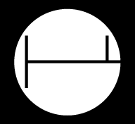
- Measuring size: Use a millimeter ruler and measure the diameter of the field of view at low magnification. Knowing this, you can estimate the diameter of fields of view at higher magnification because the diameter of the field of view at high magnification is inversely proportional to the magnification at low power.
- Explore the characteristics of your microscope and fill in Table B.2. Use a millimeter ruler to measure the field of view.
- What are the diameters of the field of view at 100×, 400× and 1000×?
- Do not rotate the 100× objective into place; instead rotate the nose piece back to the 10× objective, then the 4× objective. Lower the microscope stage using the coarse focus knob and remove the ruler.
- Drawing microscope specimens: Your microscope specimen drawings should be labeled with an appropriate scale indicating the relationship between the size of the drawing and the actual size of the object. Estimate the actual size of the specimen by comparing its length to the diameter of the field of view, and then calculate the magnification scale of your drawing. For example, if the specimen is 100 μm long and your drawing is 3 cm (= 30,000 μm) long, the magnification is 300×.
Using the Oil Immersion Lens (100×)
- Focus the image using the 40× objective.
- Rotate the nosepiece through the 100× objective to the lower 4× objective to give you a little extra space. If the 100× objective lens touches the coverslip as you rotate to the 4× objective, STOP and ask for assistance.
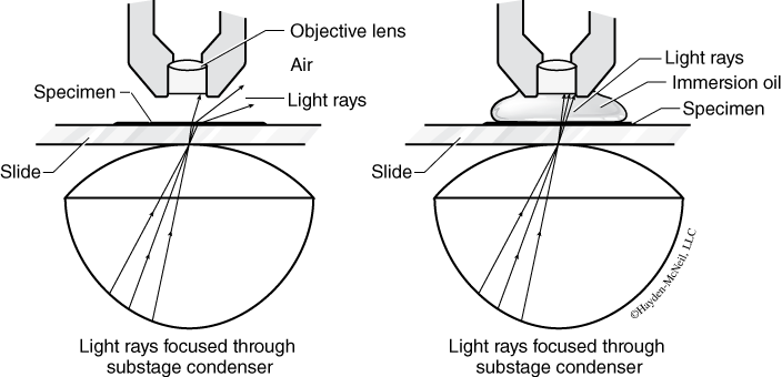
- Place a drop of oil on the top of the coverslip above the specimen. Slowly and carefully, rotate the nosepiece to position the oil immersion lens above the specimen and move it back and forth through the oil a couple of times. The lens should touch the oil, which now forms a continuous medium between the coverslip and the lens (Figure B.2).
- Focus ONLY with the fine focus knob! Adjust the light intensity and the diaphragm aperture until you have the best resolution of the specimen.
- Cleaning the immersion lens and slide: The immersion lens and slide must be cleaned with acid alcohol and lens paper. First, use dry, crumpled, lens paper to remove most of the oil; then saturate a piece of lens paper with acid alcohol and clean the remaining lm of oil from the lens using gentle circular motions. Discard the lens paper and close the alcohol bottle.
Dissecting Microscope
2. Dissecting Microscope
The stereomicroscope (Figure B.3) is a basic tool in biology labs. Unlike compound light microscopes, dissecting scopes enable you to examine features of opaque objects that are too large or too thick to see with a light microscope. Because our department has many different types of dissecting scopes, we will only provide some general rules to follow in lab. Your Instructor will assist you with the specifics of each model and type. The stereoscope is generally used with a supplementary light source called an illuminator. Both the scope and the illuminator are bulky and heavy, so carry the illuminator and the scope to your lab bench in separate trips. Use both hands when carrying the dissecting scope—hold the scope arm in one hand and the stage in the other.
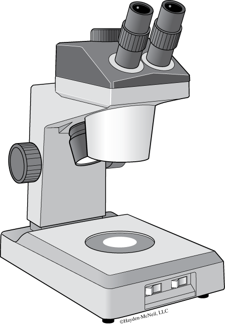
Dissecting Microscope Procedure
- Set the illuminator next to the scope and aim the light beam at the center of the stage. Place a convenient biological specimen, such as your thumb, under the light and readjust the beam of light so that it falls on the object of interest.
- Set the magnification knob on the lowest setting.
- Focus on a simple object using the focusing knob, until you see a clear image—your thumb will do for this purpose.
- Adjust the inter-pupillary distance (spacing between the pupils of your eyes) so you are able to see clearly through both lenses.
- If you cannot focus on the object with both eyes simultaneously, then do the following: Find the ocular that has an adjustable focusing ring. Close the eye that looks through this adjustable ocular and while looking through the fixed ocular, focus the image sharply using the focusing knob. Then open the “adjustable ocular” eye and close the “fixed ocular” eye. Turn the adjustment ring until you see a clearly focused image through that eye.
- Change the magnification using the magnification knob. You may have to readjust the lighting and focus.
- Choose among the materials in lab for observation with the dissecting scope and find some interesting things to show during your dissecting scope demonstration.
- Some dissecting scopes have reversible stage plates that are white on one side and black on the other. If your specimen is translucent or light in color, use the black side of the stage plate.
Making Reagents: Using Balances, Graduated Cylinders and Pipettes
3. Making Reagents: Using Balances, Graduated Cylinders and Pipettes
Nearly every biological laboratory requires certain instruments to prepare reagents. These instruments include balances, pipettes, and graduated cylinders. All of these instruments are used for weighing and measuring precise amounts of a substance. Pipettes are additionally used as a sterile way to move precise amounts of a solution from one place to another, such as from a tube to an electrophoresis gel. In this appendix you will be introduced to the balances, pipettes, and graduated cylinders—you must be able to use these tools in future labs.
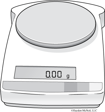
Balances
Digital electronic balances (Figure B.4) are commonplace in biology laboratories and are easy to use. However, you must take precautions to avoid making mistakes in weighing objects and avoid damage to the balance.
- Always check the maximum weight the balance can measure and never try to weigh objects that are too heavy for the balance—that will damage the instrument.
- Always avoid contaminating the balance with solid reagents, liquids, or debris—keep the instrument clean.
- Make sure the balance is plugged in and the power switch is on.
- Use a container or weigh boat to hold the substance you are weighing. Remember to weigh the container. The TARE function on most digital balances will re-set itself to zero to provide the weight of the substance only.
- When you are done with the balance, clean it, turn it off and if necessary, store it properly.
Graduated Cylinders:
- Increase the accuracy of your measured volumes by using a graduated cylinder that is closest in size to the required volume.
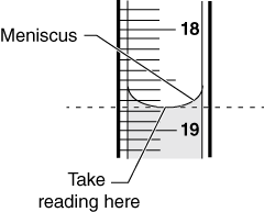
- Adhesive-cohesive fluid interactions often result in the formation of a “meniscus” or concavity at the fluid’s surface. Graduated cylinders are made to take this tendency into account, so take your readings with a graduated cylinder at eye level, to avoid parallax error, at the bottom of the meniscus (Figure B.5).
Pipettes
In BIO 204/205 you will be using four types of pipettes: micropipettes, transfer pipettes, glass pipettes, and disposable pipettes. Though they are simple tools they can be awkward to use if you are not used to them. Practice using them to avoid spills, air bubbles, and poor control due to over or under aspiration of fluids. Digital pipettors are the most precise, expensive, and easiest pipette to damage. Go over the following instructions carefully.

Purpose
Micropipettes (Figure B.6) are common workhorses in modern molecular biology laboratories. They accurately measure tiny amounts of liquids and can be used for sterile applications. They are fragile and very expensive. Learn to properly use the micropipette with the help of your lab instructor.
Review of Metric Conversions: Micropipettes usually measure volumes from 1/1,000th of a milliliter which is 1 microliter (μl) to 1 milliliter (ml). Before you can properly use a micropipette, you must be able to quickly convert from μl to ml. Complete the conversions below.
- What is the conversion factor for μl to liters? ml to liters? Place your answers in scientific notation. For example, 1 μl is 1 × 10⁻³ ml; and 1 ml is 1 × 10³ μl.
- What is the volume in microliters (μl)?
0.0057 ml = __________ μl
0.0345 ml = __________ μl
0.7890 ml = __________ μl
- What is the volume in milliliters (ml)?
2 μl = __________ ml
137 μl = __________ ml
966 μl = __________ ml
Selecting the Proper Micropipette and Adjusting the Volume
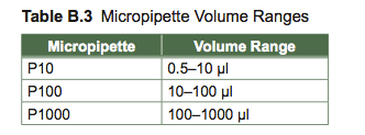
Micropipettes are selected based on their volume range. You will usually choose one of three micropipettes in a set—they are named by their maximum volume. The micropipettes are also color coordinated, corresponding with the color on their disposable tips (always use a disposable tip when using a micropipette). The top of the micropipette is usually white for the P10, yellow for the P100, and blue for the P1000 which requires white, yellow, and blue tips respectively.
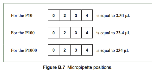
The window of a micropipette has four positions (see Figure B.7 below). Each position represents a particular decimal place. Note in the example how the decimal place changes for each of the micropipettes. In order to set the micropipette to a particular volume, you rst choose the pipette with the proper volume range. The process by which you adjust the volume can vary from one model of pipette to another. Some micropipettes require that you gently pull out the plunger on top of the micropipette, turn it to set the volume, and then push it back in to lock the volume in place. Others require you to press in a button on the side while you turn the plunger to set the volume, and release the button to lock it in place and still others adjust by just turning the plunger. Your instructor will demonstrate how to adjust your particular model of micropipette.
Which micropipette(s) would you use to measure the following volumes?
Place the name(s) in the spaces provided. 0.018 ml _________ 0.1 ml _________
What is the maximum and minimum range for each of the micropipettes listed? Check your answers with your lab instructor.

Set each micropipette to its maximum value. Next, set each micropipette to its minimum value. Note which direction, clockwise or counter clockwise, the plunger must be turned to increase or decrease the volume setting.
Pipetting Steps
It is important to master the proper use of the micropipettes—you must be able to pipette solutions accurately and ef ciently. Research labs work with tiny volumes of DNA and other macromolecules.
On most micropipettes the plunger has three stops:
- The first stop allows you to intake and expel solutions. The plunger is depressed to the rst stop to remove air from the tip. While holding the micopipette at the rst stop, the tip is immersed into the solution to be measured. When slowly released from rst position, the pipette draws the solution into the pipette tip. The solution is expelled by placing the tip over the new container and pressing to the second stop.
- The second stop is used to expel the last drop of solution from the tip.
- The third stop is used to eject the tip from the end of the pipettor into the waste receptacle.
- Micropipettes with only two stops have a separate tip ejector button.
Set your micropipette to the required volume and follow the steps below to practice pipetting water from one tube to another.
- Place the proper tip on the micropipette by positioning the barrel over the tip and gently tapping it into the tip twice; this is known as the “two tap rule.”
- Hold the tube you wish to pipette in one hand at eye level. Hold the micropipette in the other hand.
- Depress the plunger to the halfway position (first stop) to eject air from the tip.
- Place the tip into the solution and with your finger still on top of the micropipette plunger, allow the plunger to slowly return to its position as the tip fills.
- Place the tube you pipetted from into a rack and retrieve the tube you will pipette into.
- Place the liquid-filled tip halfway into the tube against one side.
- Slowly press the plunger to the first stop again and most of the liquid should release into the tube.
- Press the plunger to the second stop to release the last drop of liquid into the tube.
- Eject the tip into the proper waste container by either depressing the plunger to the third stop or pressing the tip ejector button depending on your micropipette model.
CAUTION!!
NEVER use a micropipette out of its range or you will BREAK it!
NEVER use a micropipette without a tip in place.
NEVER lay a micropipette down that has a filled tip attached. Liquid can flow into the pipette barrel and ruin the pipette.
ALWAYS use a fresh tip for every manipulation to prevent cross contamination of samples.
Chemical Solutions
This section reviews practical methods of making reagents for experiments. In scientific labs there is specific nomenclature for making solutions. In order to know how to make a solution, you must first understand molarity, percent, and concentration X.
Molarity:
Molarity describes the number of moles of a solid that is added to a liquid, usually water, for a total volume of 1 liter and the solution is described as a molar solution. If you want to make a 1 M NaCl solution (read as 1 molar sodium chloride), then you want to add enough water to 1 mole of NaCl to make 1 liter. 1 mole of NaCl is equal to the gram molecular weight of NaCl, which is 58.44 g. How would you make 1 liter of 1 M CaCl2?
Percent Solutions:
Percent solutions are made based on their weight or volume, so they can be liquids or solids. Solutions that are percent weight by volume (%w/v) are equal to g/100 ml.
- A 10% solution would therefore be 10 g of the solute, added to enough solvent (usually water) to bring the total volume to 100 ml. It is 10% because it is 10 (g) over 100 (ml).
Solutions can also be percent weight by weight (w/w) or percent volume by volume (v/v). A 10% w/w solution is 10 g of a solute added to a total of 100 g with solvent, while a 10% v/v solution is 10 ml of a liquid brought to a total of 100 ml with solvent.
- A 10% w/w of NaCl would be 10 g of NaCl brought to 100 g with water. You would add 90 g of water (which is ~90 ml). If you have a 100% glycerol solution and you want a 10% glycerol solution, then you would add 10 ml of the 100% glycerol to a total volume of 100 ml with water.
Of these three, % w/v is the most common, so that when you are asked to make a % solution it is usually referring to percent weight by volume.
Concentration X:
Laboratories frequently make stock solutions of relatively high solute/solvent concentration ratios and di- lute them to make solutions of desired concentrations. The stock solutions may be based on molarity or percent. The stock concentration of the solution is usually 2 fold or greater than the working concentration (the concentration at which the solution will actually be used). The stock solution is designated 2X, 3X, or 10X depending on its concentration, and the working concentration is usually 1X.
This method of solution preparation allows you to make large quantities of a solution just by diluting the stock with water. It also allows you to mix different solutions together to produce a final solution that is more dilute than the original solutions. For example, TBS, which is Tris-buffered saline, is made 10 fold more concentrated and referred to as 10× TBS (0.5 M Tris Base, 9% NaCl, pH 7.6). If you want to make 1× TBS (.05 M Tris Base, 0.9% NaCl, pH 7.6) then you need to dilute the 10× TBS 10 fold, or you need to add 10 ml of the 10× TBS for every 100 ml total volume.
Chemical Solution Calculations:
In a biology lab, you can make almost ALL of the solutions you need by using the following two simple equations:
1. g = mol / L * L * g / mol
Mass of solid = concentration of solution * volume of solution * molecular weight of solid
2. C1*V1 = C2*V2
Concentration of stock solution * volume of stock solution = concentration of dilute solution * volume of dilute solution
Examples
1. Your lab may keep a 60% sucrose stock solution on the shelf and you have to make 45 ml of a 40% sucrose solution from that stock. So what volume of 60% stock and what volume of solvent (water) should you mix to produce a 40% sucrose solution?
Answer: If you use Equation 2, C1*V1 = C2*V2, you know the initial concentration of your sucrose is 60% (C1), the concentration of the sucrose you want to make is 40% (C2), and the volume of 40% sucrose solution that you need is 45 ml (V2). The only value that you do not know is V1, the amount of 60% sucrose stock.
- Rearrange the equation to solve for V1 = C2*V2 / C1.
- Plug all the known values into the equation: V1 = 40%*45 ml / 60%.
- Solve for V1 : V1 = 30 ml.
- You need to bring the total volume to 45 ml, so you must add 45 ml – 30 ml, or 15 ml of water.
- If you add 30 ml of 60% sucrose stock solution to 15 ml of water you will have 45 ml of a 40% sucrose solution. Please note that the final solution is always more dilute (less concentrated) than the stock solution.
- How would you check your answer?
2. How many grams of KOH are needed to make a 2 M solution?
Answer: A two molar potassium hydroxide solution would contain (2 × 56.11) grams of KOH made up to 1 liter of solution.
3. How many grams of solute would you need to make 500 ml of 0.4 M CuSO4 solution?
Answer:
- Cu = 63.546 atomic mass units
- S = 32.06 atomic mass units
- O = 15.999 atomic mass units
- Therefore, one mole of CuSO4 weighs 159.602 g
- Using equation 1: X grams solute = 159.602 g × 0.4 M × 0.5 liters
- Therefore, 31.9204 grams of CuSO4 made up to 500 ml of solution with water
Spectrophotometer
4. Spectrophotometer
Why are spectrophotometers useful in biology?
- You can measure the rate of a biochemical reaction.
- You can measure the concentration of DNA or protein in solution.
- You can quantify a change in color.
- You can count the number of cells (such as bacteria) in a solution.
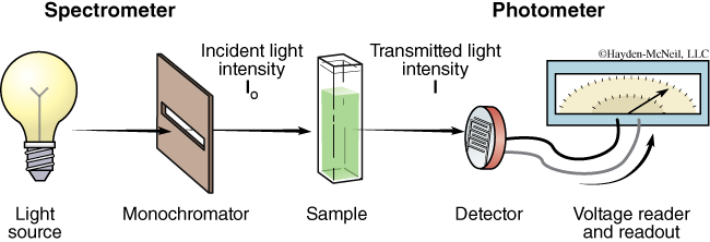
Spectrophotometers are scientific instruments commonly found in biology laboratories. A spectrophotometer is really a combination of two instruments: a spectrometer and a photometer (see Figure B.8). A spectrometer produces light of a selected wavelength (color or wavelength), and a photometer measures light intensity. You will use spectrophotometers to shine a wavelength of light onto biological samples and measure the amount of light that passes through the sample.
In the spectrophotometer, the light source gives off radiation of different wavelengths. Usually a tungsten lamp is used for the visible light range, and a deuterium lamp for the UV range. The selection of light at one particular wavelength is done with a monochromator, which consists of a prism or diffraction grating (and also a filter for visible light). The sample is placed in a cuvette of a defined width. The cuvette is made of glass for visible light and quartz for ultra-violet light, since glass is opaque to UV. The detector of the photometer is usually a photodiode that measures the intensity of the light transmitted and sends a voltage signal to a display device, normally a galvanometer.
The amount of light that shines through the sample is transmitted (or scattered) light; and the amount of light that does not shine through the sample, or is blocked by the sample, is the absorbed light. The reduction in amount of light from I0 to I, (as seen in Figure B.8) is due to a number of factors, other than the sample itself, including the reflection from the walls of the cuvette. Scientists take considerable precautions to keep such confounding factors constant to reduce the variation between different samples. The sample itself is primarily responsible for this reduction of light in that the absorbance varies according to solvent, solute, and solute concentration in the sample solution. Absorbance is unitless and is expressed as Aλ where λ is the specific wavelength of light used in making the measurement.
Transmittance and Absorbance
I0 is the symbol used to represent the amount of light striking a sample—the incident light intensity. I stands for the amount of light which passes through the sample—the transmitted light intensity. Transmittance (T) is the percent of light that passes through a sample divided by the amount of light that you shined onto that sample. T = I / I0
For example, if you shined 50 lumens (measure of light, or brightness) onto a sample and 10 lumens passed through the sample, then the transmittance would be 20% because:
Transmittance is the ratio of I / I0 and any ratio can also be expressed as a percentage by multiplying it by 100:
(10/50 = 0.2 *100 = 20%)
Why do we calculate absorbance (A)?
Absorbance is the capacity of a substance to take up, or absorb, electromagnetic radiation, or in our case, light. The Beer-Lambert law describes the relationship between absorbance (A), incident light (I0), transmitted light (I), and transmittance (T):
Another expression of the Beer-Lambert law is:
A = c d ε
Although this might at first appear to be a poor attempt at the alphabet, it actually represents an extremely useful expression for biologists, where A = absorbance (unitless), c = molar concentration (mol*L–1), d = path length of light (cm), and ε = molar extinction coefficient (L*mol–1*cm–1). The molar extinction coefficient is specific to the chemical properties of the sample, the wavelength of incident light, the solvent used and possibly the pH of the solution. At the maximum wavelength of light, the molar extinction coefficient for a solution of CuSO4 in water is ~20 M–1 cm–1, chlorophyll in water is ~60,000 M–1cm–1 at 362 nm, and if chlorophyll is placed into methanol, ε >100,000 M–1cm–1 at 780 nm.
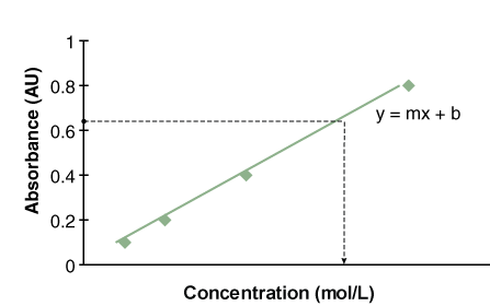
If you already knew the molar extinction coefficient for a particular sample, then you could measure the sample’s absorbance and calculate its concentration using the equation above. The main problem is the difficulty in determining the molar extinction coefficient for your sample, because of the reasons mentioned above. An alternative is to create a standard curve (Figure B.9). The absorbance at known concentrations of your sample are measured, graphed, and the equation for your standard curve is derived. You then measure the absorbance of your sample of unknown concentration and calculate the concentration for your unknown sample. For the samples used in BIO 204 and 205, the relationship between absorbance and concentration will be linear.
What are the assumptions of the Beer-Lambert Law?
- Incident radiation is monochromatic; one wavelength of light is shined on your sample.
- Absorption occurs in a uniform medium; your sample is well mixed.
- Absorbing molecules behave independently; each molecule acts independently as it absorbs radiation.
What is the relationship between Absorbance and Transmittance?
Transmittance is a measure of how much light passes through a sample and so the range of transmittance is from 0 (opaque sample) to 1 (or 100% of the light passes through the sample).
Absorbance is a measure of how much light interacts with the sample and so the range of absorption is from 0 (none of the light interacts with the sample) to infinity (all of the light interacts with the sample).
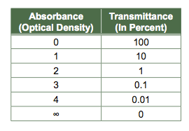
In this course, you will never use a sample that has an infinite absorption of ALL wavelengths of light. The table above may help you understand the logarithmic relationship between absorbance and transmittance.
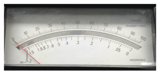
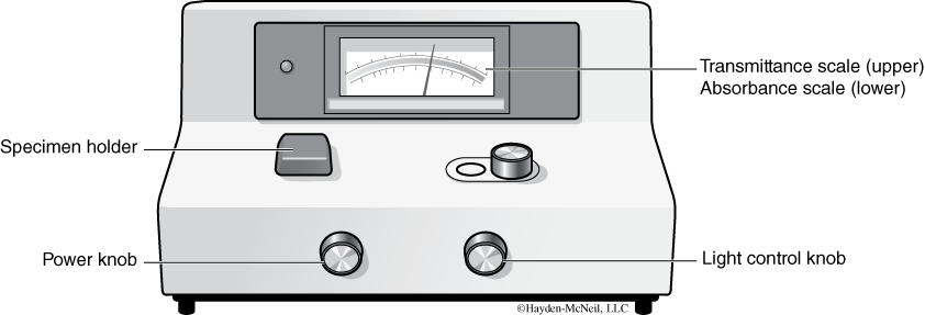
The spectrophotometers used in our labs (Spec 20s) have two scales (see Figure B.10). One is calibrated arithmetically for transmittance (0 to 100%) and the other is calibrated logarithmically for absorbance (infinity to 0). Although absorbance theoretically reads to infinity, the highest calibrated absorbance reading is 2.0.
What properties cause the sample to absorb light?
The ability of a molecule to absorb light depends on its chemical structure. Molecules with conjugated double bonds, especially with electrons delocalized in a ring structure (like benzene), usually absorb light in the visible and UV range of the spectrum. This applies to macromolecules such as DNA because of its pyrimidine and purine bases; proteins, because of the peptide bond and the aromatic amino acids tryptophan, phenylalanine, and tyrosine; as well as pigments like chlorophyll due to the tetrapyrrole rings.
Standardizing the Spectrophotometer (Spec 20)
Purpose
Before you can expect to get accurate sample readings from the spectrophotometer, you must first standardize it—this activity shows you how. To get accurate readings, you also must keep the sample lid on the spectrophotometer closed except when you are inserting or removing tubes from the instrument. Keep the lid closed when you are taking readings.
Spectrophotometer Procedure
- Turn on the spectrophotometer by turning the power control knob (see Figure B.11) to the right. Let the machine warm up for 10 minutes.
- Fill a blank control tube “B” with 4 ml of diluent only (this tube is usually your control tube in experiments). Make a small black mark at the edge of the test tube. You will use this mark to align the tube in the sample holder in the same orientation each time you make a reading.
- Record the fixed spectrophotometer wavelength (λ = ______).
- Zero the Spec 20: After a 10-minute warm-up, with the sample holder lid closed and no test tube in the sample holder, zero the Spec 20 by adjusting the power control knob to zero transmittance (Absorbance (abs) = ∞ = in nity).
- Standardize the absorbance range: Use a Kimwipe to clean the Tube “B” (blank). Handle the tube with Kimwipes only. Open the sample holder lid and insert the “B” tube into the sample holder. Align the mark on the rim with the raised line at the edge of the sample holder and close the lid (by orienting the tube the same way at each reading you avoid data artifacts created by irregular light transmission through the test tube). After inserting the test tube in the holder, a window in the Spec opens and light shines on the tube.
- Adjust the light control knob so the meter reads 0.0 absorbance (100% transmission). Remove Tube “B” and close the lid. The spectrophotometer is now standardized for reading absorbance.
100% transmittance (Abs = 0) when the sample holder contains a tube of clear diluent like water and
0% transmittance (Abs = ∞) when the sample holder is empty.
- Wipe your sample tube with a Kimwipe. Orient your sample tube properly in the sample holder and read the absorbance. The accuracy with which you can read the absorbance is halfway between any two marks. For example you can read 0.185 or 0.190, but not 0.187.
Vernier Calipers
5. Vernier Calipers
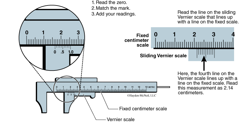
Unlike rulers that can measure to the nearest millimeter, a Vernier caliper (Figure B.12) has a sliding scale that makes it possible to measure to a tenth of a millimeter—that’s an extra significant digit!
Vernier Caliper Procedure
- Use the fixed metric scale to read to the nearest centimeter and millimeter.
- To read the nearest tenth of a millimeter, use the sliding Vernier scale and find the line on the sliding scale that lines up with a millimeter line on the fixed scale. The line on the sliding scale is the desired tenth of a millimeter reading.
- Choose five items from the lab, measure them using the Vernier caliper, and enter this data into an Excel spreadsheet.
pH Meter
6. pH Meter
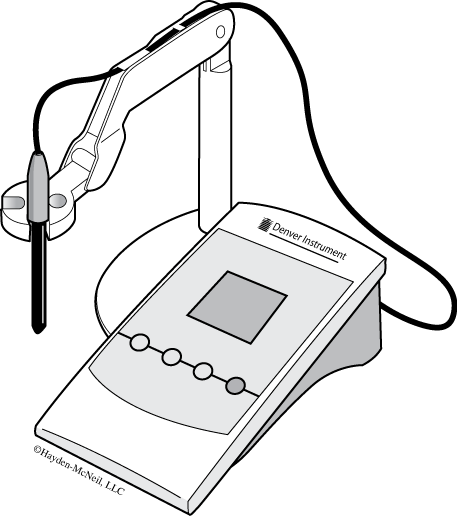
A pH meter (Figure B.13) is a voltmeter that measures the potential difference between two glass electrodes: a reference electrode that usually contains a solution of AgCl2 and a sensor electrode that usually has a glass membrane that allows hydrogen ions to pass through it. The pH meter reads this small voltage difference across the glass membrane between the reference electrode and the test solution outside the electrode into a direct pH reading. It is important to make sure the electrode does not dry out since the AgCl2 concentration will change and affect the meter’s voltage readings. At neutral pH, there is no voltage difference across the membrane—a properly calibrated meter gives a pH reading of 7. At alkaline pHs, the voltage difference is relatively negative and at acidic pHs, the voltage difference is relatively positive. The standardization procedure sets these voltage differences using reference solutions with known pHs.
Preparing the pH Meter
- Check to be sure that the pH meter is plugged in.
- Check that the electrode is plugged in to both the “input” and “ATC” connectors.
- Check that the fill hole at the top of the electrode is in the “open” position.
- Press “Setup” once, see display “Clear buffers,” then press Enter to clear any stored buffers.
Standardizing the pH Meter
To ensure accurate pH measurements, you must standardize your meter using reference solutions of known pH. Standardize the meter using, minimally, two standard solutions in the pH range of your samples (i.e., to test acids, use reference solutions pH = 4 and pH = 7). Between pH measurements, rinse the electrode with RO water and gently blot excess water with a Kimwipe, but do not dry the electrode.
pH Meter Procedure
- Standardize Meter: Press the “Setup” button twice. Screen displays “set buffers” and buffers (2 4 7 10 12). Press “Enter” to select.
- Rinse electrode with RO water. Use a Kimwipe and blot excess water. Gently! Do not press or rub the delicate glass bulb.
- Immerse the electrode in the standard pH 7 reference buffer first because this sets the zero on the pH meter. Gently swirl the buffer while the electrode is immersed until an “S” is displayed above and to the left of the pH reading indicating the reading has stabilized.
- Press “Standardize.” Standardization is complete for pH 7 when a small corresponding number “7” is displayed below the pH reading. Record the slope. If the slope is > 0.9, it is reasonably accurate.
- Repeat steps 2 to 4 for the pH 10 and pH 4 standard buffers. Record the slopes in your lab notebook after each standardization. If you do not receive an error message, you have successfully completed a 3-point (pH 4, 7, and 10) standardization of your pH meter.
- Rinse the electrode with RO water and gently blot excess with a Kimwipe. Now you are ready to read the pH of your sample.
Testing pH of Solutions
Test the pH of two solutions available in lab. Based on what you know of particular solutions, make a guess as to whether or not the solutions you are provided with are acidic, basic, or neutral before you use the pH meter. Are there any solutions whose pH surprised you? Why?
Centrifuge
7. Centrifuge
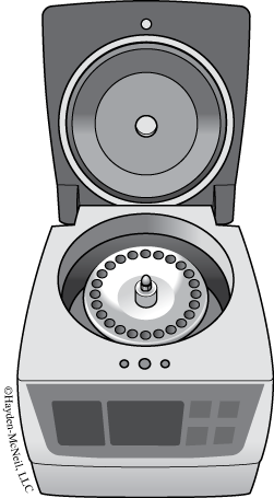
You have probably experienced centripetal acceleration (force) before. You know those carnival rides—the ones with the swings, that swing in a circle going faster and faster? That ride follows the same physical principles as a the table top centrifuge in a biology laboratory. The table top centrifuge goes much, much faster, however. This appendix will introduce you to the basic principles behind centrifuge technology, including how it works, why you might need a centrifuge, and how to operate one safely.
Safety Guidelines
- Always make sure that the centrifuge is positioned on a level surface.
- Always balance (see below) the load of samples you are running, using blanks if necessary.
- Be sure the internal lid (if present) fits securely over the samples.
- Be sure that all samples are safely contained within the rotor wells, i.e., caps are not sticking up or poking out of the internal lid. When spun at high speeds, any pieces not contained will likely break off and could damage the machine as well as your samples.
- Be sure that your samples are contained in centrifuge tubes (have tapered ends) that fit the size centrifuge you are using. Check to make sure that the caps on your tubes are closed securely. If the tube is uncapped or becomes uncapped while spinning, your sample could end up on the centrifuge walls, rather than contained within its tube. This not only sets your experiment back, but can permanently damage the centrifuge if moisture or particles get into the mechanical workings.
- Do not open the lid until the rotor has completely stopped spinning. Most centrifuges have locks to prevent you from opening the lid while the rotor is spinning. Due to the high speed of the rotor, there is the potential for tubes to fly out, especially if the centrifuge is not balanced properly.
- Never touch the spinning rotor of a centrifuge. This can cause serious injury, damage the machine, and/ or your samples. Wait until the rotor has come to a complete stop before opening the lid or removing tubes.
Balancing Guidelines
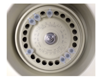
In order to properly operate a centrifuge, the samples contained inside must be balanced by mass. Small differences in the mass of samples can lead to large force imbalances when spun at high speeds. An imbalance in a spinning centrifuge can lead to wobbling, which puts stress on the spindle holding the rotor in place. Enough stress will cause the spindle to break and rotor could fly off at high speeds, damaging not only the centrifuge, but surrounding equipment and personnel. Thus, balancing is of chief importance. For every sample you place in the centrifuge, directly opposite it should either be another sample of equal mass or a blank of equal mass (Figure B.15). Here are some balancing tips:
- A large portion of the mass comes from the tube. Make sure you utilize the same brand and style of centrifuge tube for your samples and blanks.
- The rest of the mass comes from the sample in the tube. For most purposes the volume of the sample is a sufficient measure to use as a balancing reference. This assumes the solutions have similar densities. For example, if you have 200 μl of water the tube across from it should contain 200 μl of water. If you use 200 μl of glycerol, then the tubes will not be balanced because glycerol has a higher density (~1.26 g/ml) than water (~1 g/ml).
- Knowing that you need to balance samples could play into how many samples you run at a given time. You should make note of your centrifuge’s capacity, how many samples you would like to run, the volumes of those samples, and how many blanks you will need. If all of your samples contain the same volume, you can use them to balance each other.
- You can place samples of different total mass in the same centrifuge, as long as they are all individually balanced appropriately.
- The wells in a centrifuge are typically labeled with a number. Make sure you know how many wells there are total, and which wells are directly opposite each other. Sometimes it is difficult to visually line them up, especially when using a centrifuge with a large rotor. For example, if there are 24 wells in the rotor, well #13 is directly opposite well #1. In this same example, what well is directly opposite well #15? What about well #7? If the blank is even one well off from being directly opposite, the centrifuge will not be balanced.
- Centrifuges with a total number of wells divisible by three will allow centrifugation of odd numbers of tubes of equal mass. You can balance 5 tubes in a 24-well rotor by placing 3 tubes equidistant around the rotor (for example, positions 1, 9, and 17) and the remaining 2 tubes across from each other (for example, positions 6 and 18).
Labeling Tubes
Don’t count on your ability to remember which tube is in which rotor well. Always label your tubes clearly and concisely, both on the lid and the side, so that you are able to tell them apart no matter what order you remove them from the centrifuge.
Speed
Most centrifuges run on two different speed scales, rotations-per-minute (RPM) and relative centrifugal force (RCF). RPMs are exactly what they say they are—the number of full rotations made in one minute. Most tabletop centrifuges can be set in intervals of 100 rotations per minute. Be aware of the minimum and maximum speeds of the centrifuge you are working with. Each protocol requires a specific speed. Too slow, and your precipitate will not pellet. Too fast, and you may precipitate unwanted particles or destroy the integrity (e.g., pulverize a cell) of your sample. You should know how these two speeds relate to each other (see equation 1 below) and which is required in the protocol you are following. Always double check the set speed before starting a centrifuge, as it is relatively easy to toggle between RPMs and RCF. RCF is also termed g, e.g., “spin samples at 5 gs,” after the gravitational acceleration. See the following equation:
Timing Guidelines
The centrifuges you will use have timers on them to automatically stop spinning the samples after a particular amount of time has passed. You want to make sure you only centrifuge your samples for as long as necessary. Too long or too short times could lead to erroneous results. Follow the protocol you are using precisely for best results.
Temperature Guidelines
Some centrifuges have temperature controls to maintain a specific internal temperature of the spinning chamber. Check the protocol you are following for any specific temperature requirements of the samples you are spinning and adjust your experiment accordingly.
Activity—Will It Centrifuge?
Centrifuge various solutions available in lab. If you are given a specific protocol, follow the instructions to centrifuge your samples at the appropriate speed for the appropriate amount of time. If you simply want to visualize the effects of centrifugation, try spinning the same type of sample (e.g., 200 μl of pond sediment) at several different speeds and time settings. Compare your results from each run of the centrifuge. Make notes of the speed and time you used, the solution and volume you were working with, and describe the result. It may also help to draw a picture.
- You may not see any change in the sample, no matter how fast or how long you spin—What properties of solutions do you think affect the “ability” of a precipitate to form during centrifugation?
- Do not centrifuge any solutions that have not been expressly approved by your instructor.