 14.1 Geospatial Lab Application3D Modeling and Visualization
This chapter’s lab will introduce you to concepts of modeling and design using three-dimensional objects. Working from an aerial image of a building with spatial reference, you will design a building in 3D using SketchUp, incorporating accurate height measurements, textures, and other effects, and place it in its proper location in Google Earth. While there are many methods that can be used for designing a building (including Google’s Match Photo tools), this lab will show you how to use a variety of SketchUp tools through the active process of creating a building.
Important note: Even though this lab uses a fixed example, it can be personalized by selecting another structure you’re more familiar with—such as your home, workplace, or school—and using the same techniques described in this lab to design that structure instead.
As in Geospatial Lab Application 7.1 there are no questions to answer—the product you’ll create in this lab will be a 3D representation of a building in SketchUp, and you’ll place a version of it in Google Earth. The answer sheet for this chapter will be a checklist of items to help you keep track of your progress in the lab.
Objectives
The goals for this lab are:
 to obtain imagery to use in a design environment.
- to familiarize yourself with the uses of the SketchUp software package, including its operating environment and several of its tools.
- to apply textures to objects.
- to utilize components in 3D design.
- to transform your 3D model into the KMZ file format, and place it in Google Earth.
Using Geospatial Technologies
The concepts you’ll be working with in this lab are used in a variety of real-world applications, including:
- urban planning, where 3D models make it possible to visualize new development projects, assess the visual impact of new buildings on the surrounding area, and to develop projects that will be in character with the cityscape.
- archaeology, where 3D modeling can be used to recreate ancient cities, and the layouts of archeological sites.

Obtaining Software
- The current version of SketchUp is available for free download at http://www.sketchup.com/.
- The current version of Google Earth (7.1) is available for free download at http://earth.google.com.
Localizing This Lab
Important note: Software and online resources sometimes change fast. This lab was designed with the most recently available version of the software at the time of writing. However, if the software or Websites have significantly changed between then and now, an updated version of this lab (using the newest versions) is available online at http://www.whfreeman.com/shellito2e.
Lab Data
There is no data to be copied for this lab. You will, however, use the “Bird’s eye” imagery from Bing Maps (see Hands-on Application 9.5: Oblique Imagery on Bing Maps), so start that up in a Web browser.
In this lab you will design a 3D model of a building on Youngstown State University’s (YSU’s) campus, and then view it in Google Earth. In Section 14.2, you will take a “snapshot” of the building to start with. Rather than examining a campus building at YSU, you can start at this point with a base image of any local building—such as the school building you’re in, a nearby landmark or government building, or your house. You can use the same steps in this lab and the SketchUp tools to design any building or structure you so choose in place of the one used in this lab—the same lab techniques of using SketchUp will still apply, you’ll just have to adapt them to your own 3D design needs.
466
14.1 Starting SketchUp
- Start SketchUp. Select the option for Choose Template, and then from the available options select Google Earth Modeling—Feet and Inches.
- There are several different templates available, depending on what type of 3D design you want to do.
- Next, select the Start using SketchUp button.
- SketchUp will open into a blank working environment, with three intersecting lines at the center. These represent the axes you will use for 3D design—red and green are the horizontal (x and y) axes, while blue is the vertical (z) axis.
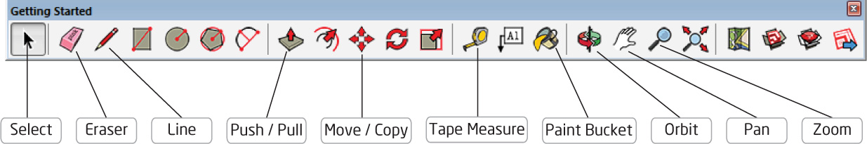
- You’ll see the SketchUp toolbar at the top of the screen. You’ll use many of these tools during the lab—the tools that you’ll use most often in this lab (from left to right on the toolbar) function as follows:
 (Source: Sketchup Make/Trimble)
- The black cursor is the Select tool that lets you choose or select objects.
- The pink eraser is the Eraser tool that allows you to remove lines and objects.
- The pencil is the Line tool that lets you draw, or construct, lines.
- The box with the red arrow coming up from it is the Push/Pull tool that allows you to alter the shape of polygons.
- The four red arrows represent the Move/Copy tool that can be used to drag objects around the screen and also to create copies of objects.
- The extended yellow tape measure is the Tape Measure tool that allows you to measure the length or width of objects.
- The bucket spilling paint is the Paint Bucket tool that allows you to change the color or texture of objects.
- The swirling red and green lines around the pole represent the Orbit tool that allows you to change your view and maneuver around the scene.
- The hand is the Pan tool that allows you to move around the view.
- The magnifying glass is the Zoom tool that allows you to zoom in and out of the scene.
- There is another specialized tool (Add Location) that you’ll make use of, but the lab will point this out to you when you need it.
14.2 Obtaining Google Imagery
SketchUp can use Google imagery as a starting point for your design work in SketchUp, and then you can transfer your 3D structures into Google Earth (GE).
- To begin, start Google Earth.
Important note: This lab will have you design a simplified representation of Lincoln Building (formerly known as Williamson Hall, the original College of Business building) on YSU’s campus. All of the measurements of things like heights, window lengths, window measurements, and so on are either just approximations or values generated for this lab and for use only in this simplified model. To use real values for Lincoln (or your own buildings) you would have to make measurements of the structure or consult blueprints for actual heights and sizes. - Lincoln Building is located on YSU’s campus at the following latitude/longitude decimal degrees coordinates:
- Latitude: 41.103978
- Longitude: −80.647777
- Zoom GE into this area and you’ll see the top of the building (see the following graphic). Fill the GE view with the entirety of the building and return to SketchUp. This should give you a good look at the overhead view of the Lincoln Building for reference in the next step. You’ll use GE later, so minimize it for now.
 (Source: Google)
 - Back in SketchUp, select the Add Location icon from the toolbar:
 (Source: Sketchup Make/Trimble)
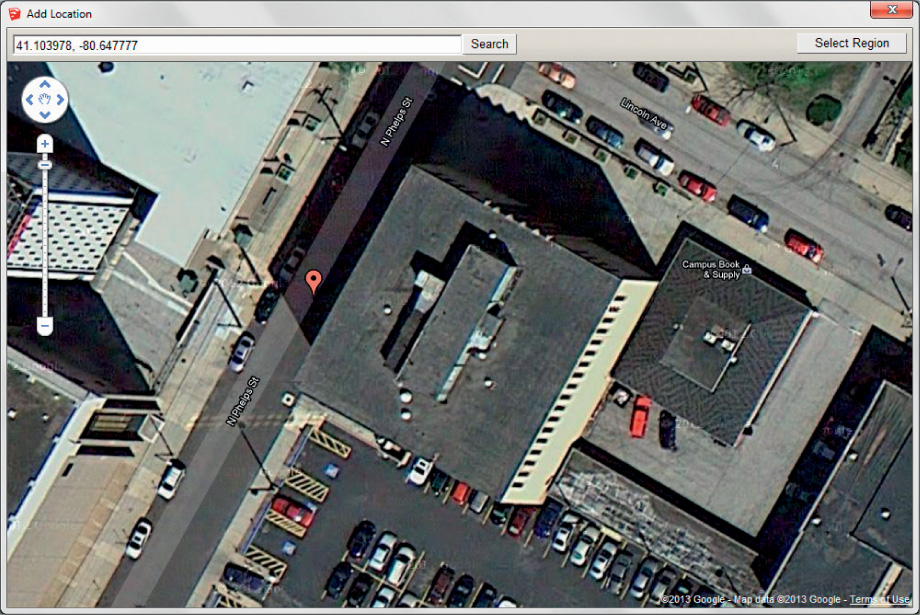
 - Add Location allows you to take a “snapshot” of Google imagery and import it (with information on the coordinates of the view as well as terrain information) into SketchUp, for use as a digitizing source.
- In the Add Location box that appears, type the coordinates of Lincoln Building and click Search. Use the zoom and pan tools (which are the same as the Google Earth tools) to expand the view, so that you can see all of Lincoln Building in the window (as you just did in Google Earth).
 (Source: Sketchup Make/Trimble)
 - When you’ve got the view set up how you want it, click the Select Region button.
- A new image will appear—a bounding box with blue markers at the corners. Drag the corners of the box so that it stretches all the way across Lincoln Building (like in the following graphic). This area will be the “snapshot” that SketchUp will take of the imagery, and that you’ll use in the modeling process—so be sure to capture the whole area.
 (Source: Sketchup Make/Trimble)
 - When everything is ready, click Grab.
- After the importing process is done, the image (in color) should appear in SketchUp, centered on the axes.
 (Source: Sketchup Make/Trimble)
 - In SketchUp, you can turn the terrain on and off within the snapshot. From the File pull-down menu, select Geo-location, and then select Show Terrain. You’ll see a bit of warp and change added to the image, indicating that the terrain (that the image is draped on) is turned on. You can use this menu option to toggle the terrain on and off by placing a checkmark in that menu option. For now, toggle the terrain off (so the image is perfectly flat).
470
14.3 Digitizing the Building Footprint
- You can digitize the dimensions of Lincoln Building directly from the imported aerial view. The easiest way to do this is to position the view so that it’s looking directly down on the image. From the Camera pull-down menu, select Standard Views, then select Top.
- The view will switch to show the image as seen from directly above. To zoom in or out so that you can see the entire building, select the Zoom icon from the toolbar (or if your mouse has a scroll wheel, you can use that to zoom as well). To zoom using the icon, select it, then roll the mouse forward or back to zoom in and out.
- When you can see the outline of the entire building, it’s time to start digitizing. Click on the Pencil icon (the Line tool) on the toolbar to start drawing.
- Your cursor will now switch to a pencil. Start at the lower left-hand corner of the building and click the pencil onto the building’s corner. A purple point will appear. Now, drag the pencil over to the lower right-hand corner and hover it there for a second. The words “on face in group” will appear. This is SketchUp’s way of telling you just what surface you’re drawing on (in this case, the face is the surface of the image).
- Click the pencil on the lower right-hand corner, then at the upper right-hand corner, then at the upper left. The guide may change to “Perpendicular to the edge,” indicating that you’ve drawn a perpendicular line. Finally, drag the pencil back to where you started. When you reach the beginning point, the cursor should turn green and the word “Endpoint” will appear. This indicates that you’ve closed the polygon of the building’s footprint in on itself. Click the pencil at the endpoint and the polygon will appear, covering the entire building.
Important note: If you have only lines and not a complete polygon, return to the lower corner and remake the footprint polygon. (Source: Sketchup Make/Trimble)
471
14.4 Extruding the Building Footprint
- With the building’s footprint successfully digitized, the next step is to give it some height.
- From the Camera pull-down menu, select Standard Views and select Iso. The view will switch to a perspective view.
- From the toolbar, select the Push/Pull tool.
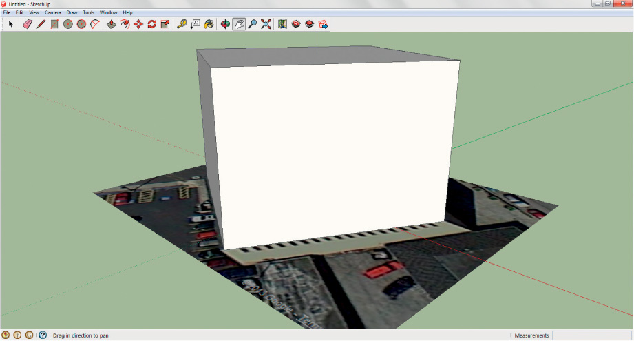
- Your cursor will change again. Hover it over the footprint polygon and you’ll see it slightly change texture. Click on the footprint and hold down the mouse button, then use the mouse to extrude the polygon by pushing forward.
- In the lower-right-hand corner of SketchUp, you’ll see the real-world height you’re extruding the building to. Lincoln Building is approximately 72 feet high. During the extrusion operation, you can type 72′ and hit the Enter key on the keyboard while holding down the mouse button, and the polygon being push/pulled will automatically extrude to that height.
 (Source: Sketchup Make/Trimble)
 - You can double-check the measurement by selecting the Measure Tape icon from the toolbar.
- Click the measuring tape at the base of the Lincoln Building block and drag it to the top. The measurement (in feet and inches) will appear. You can use the push/pull tool to readjust the building height if necessary.
14.5 Maneuvering in SketchUp
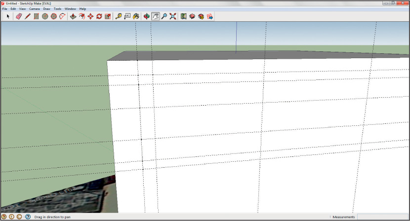
- An easy way to maneuver and examine the 3D objects you’re creating is to use the Orbit and Pan tools, which are available on the toolbar.
- Use the Pan tool (the hand) to drag the current view in any direction.
- Use the Orbit tool (the red and green arrows curved around a pole) to rotate the view around an object.
- Practice with the two tools for a couple of minutes to get used to the feeling of maneuvering in the SketchUp environment.
- Maneuver around so that you can view the front of the building (the part that opens onto the street).
14.6 Toggle Terrain
- For this simplified example, we’ve been assuming the terrain under Lincoln Building is completely flat. When the Google image was imported, it included data about the terrain built into the image. You will probably want to take terrain into account early in the process if you’re modeling a structure or object built into a hill, or located on sloping terrain, so that measurements and features will match up properly.
- To examine the “real” terrain about Lincoln Building, toggle the terrain on (again, select the File pull-down menu, then choose Geo-location, and then activate Show Terrain.
- Orbit around the building and you’ll see that some of the back corners appear to be slightly “floating” over the terrain. To rectify this, orbit underneath the building and the image and use the Push/Pull tool to slightly “pull” the building down below the image. This will ensure that the building extends completely into the ground and that none of it will appear to float over the terrain.
14.7 Adding Features to the Building
- Use Bing Maps’ “Bird’s eye” feature to get a closer look at Lincoln Building. Viewing from the north, you may be able to see a recessed entranceway leading into the front of Lincoln Building.
- Set up the entranceway approximately 27 feet (27′) across, and set it to begin approximately 34 feet (34′) from each side of the front of the building. The opening itself is about 9 feet (9′) tall. This is the size of a block you want to draw on the front of the building.
- In order to find these dimensions, you can use the Tape Measure to create some guide lines (or “construction lines”) on the face of the building.
- Select the Tape Measure icon and start from the lower left corner (as you face the building). Measure upward approximately 9 feet, and then double-click the mouse.
Important note: A more precise way to use the Tape Measure is to type 9′ (for 9 feet) while dragging the tape in the direction you want to measure. A small mark will appear at the 9′ length, and you can use that as a marker for more measurements. - Next, drag the mouse over to the other side of the building and double-click. A dashed line will appear on the face of the building at a height of 9 feet. This is a construction line—it’s invisible in the modeling process, but it’s useful for drawing measurements.
- Starting along one side of the building, measure across 34 feet, double-click the mouse, and then measure down to the base of the building. Do the same on the other side. You should have construction lines set up that block out the entranceway on the face of the building.
 (Source: Sketchup Make/Trimble)
 - If you find you’re creating too many construction lines, you can always select them with the cursor icon and delete them by using the Eraser icon on the toolbar (in fact, anything you create can be removed by using the eraser).
- Now, use the pencil to draw the entranceway on the face of the building, tracing over the construction lines.
- Finally, select the Push/Pull tool and use it to recess the entranceway by approximately 6 feet. Use the mouse to push the block inward, and watch the distance bar in the lower right corner.
- Examine the building with Bing Maps’ Bird’s eye imagery, and you’ll see that Lincoln Building has several sets of windows that run around the top of the building—two sets of four windows on the front and back, and 18 windows on either side. Drawing all 52 of these identical windows individually would be a huge chore, so to save time and effort, you’ll be designing the window only once and reusing it throughout the model.
- One way of doing this is to set up multiple construction lines across the front of the building. Orbit around to see the top front of the building. Set up construction lines as follows (these are simplifications of the real measurements for purposes of this lab):
- The first window begins 6 feet from the edge of the building.
- The first window begins 3 feet from the top of the building.
- The window is 3 feet wide and 21 feet tall.
- There are five divisions on the window, and their measurements are (from the top):
- 2 feet
- 5 feet
- 7 feet
- 5 feet
- 2 feet
 (Source: Sketchup Make/Trimble)
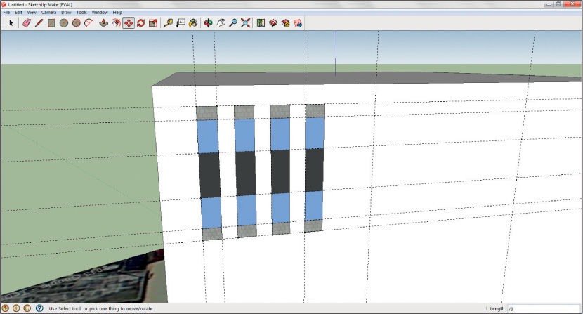
 - Next, draw the outline of the window and the five divisions, by using the Pencil tool in conjunction with the construction lines.
- With the outlines drawn, it’s time to make it actually look like a window by adding some textures.
- Select the Paint Bucket icon from the toolbar.
- A new window of Materials will open. These are the various textures that can be “painted” on a face. For the purposes of this simplified model, select Asphalt and Concrete from the Materials window pull-down menu, then select the option for Concrete_Block_8x8_Gray. Back in the model of the window, click the paint bucket on the top and bottom sections of the window. They should change appearance to a “concrete block” finish.
- Next, select Translucent from the Materials window pull-down menu and choose the option for Translucent_Glass_Blue. Click on the second and fourth blocks of the window with this new material.
- Lastly, choose Colors from the Materials window pull-down menu, select Color_007 (it’s a black color), and then click on the final (third) section of the window. All five sections of the window should now be colored in. You can now close the Materials box.
 (Source: Sketchup Make/Trimble)
14.8 Working with Components
As we noted before, you’ve created one window, but the model requires a total of 52 of them across the four sides of the building. If you’re going to re-use something many times, the easiest option is to create a Component out of the object.
- Select the Cursor icon and drag a box over all sections of the window. They’ll become highlighted in blue, signifying they’re now selected. Be very careful not to select any of the building faces themselves—you want only the sections of the window. (To de-select items, hold down the Shift key and click on the items with the mouse.)
- Right-click on the selected window and choose Make Component.
- In the Create Component dialog box, type in the name “Lincwind” for the new component.
- Select Any for “Glue to” from the drop-down box.
- Place a checkmark in the Cut opening option.
- Place a checkmark in the Replace selection with component box.
- Click Create when you’re done.
 (Source: Sketchup Make/Trimble)
 - The selected section of the window will now be a SketchUp Component and it will be stored for later use in the model.
14.9 Making Multiple Copies
Now that the window is a component, it’ll be easy to work again with the same item. In this section of the building, there are four windows, each approximately 2.5 feet apart and 3 feet wide. What you’re going to do is make multiple copies of the component window, then have SketchUp automatically space out the windows for you.
- Create a construction line 13.5 feet away (the space of two window lengths and the distances between them) from the window’s edge, stretching from the top to the bottom of the building. This is where the copy of the window will go.
- Next, use the cursor to select the window component. It will be outlined in blue when it’s selected.
- Next, choose the Move/Copy tool from the toolbar.
- The cursor will change to the new icon.
Important note: Hold down the Ctrl key on the keyboard—this tells SketchUp you want to copy the window instead of moving it somewhere. If you don’t hold down the Ctrl key, SketchUp will try to move the window somewhere else instead of making a copy. - Use the mouse to select and drag the copy of the window over to the right of the new 13.5-foot distant construction line. Make sure that the inference dialog box that will appear indicates that you’re copying it “On the Face” (that is, the copy will be moved to the face of the building, instead of into space somewhere).
- Once the copy of the window is positioned properly, type /3 on the keyboard. This will tell SketchUp to make a total of three copies, evenly spaced between the original and the location of the new copy. You will now have four windows on the front left-hand side of the building.
 (Source: Sketchup Make/Trimble)
 - Now it’s time to put windows on the other side of the front. Create a construction line 6 feet from the right-hand side of the building.
- To add the component of the window, select Components from the Window pull-down menu.
- In the Components dialog box, select the “house” icon (under the Select tab) to utilize only those components that exist in the current model (the only component should be your “Lincwind” window).
 (Source: Sketchup Make/Trimble)
 - Click on the component itself in the window and drag it onto the face of the building in the model, positioning it properly in conjunction with the construction line you just drew.
- Now, repeat the previous steps (draw a construction line 13.5 feet away and copy the windows, creating a total of three copies properly spaced out the correct distance from one another).
- You should now have two sets of four windows each on the front of the building.
- Rotate to the back of the building. You’ll want to create the same layout (two sets of four windows each), using the same measurements on the back face of the building.
- Next, rotate to one side of the building. Each side of the building has 18 windows on it, so you’ll use the same technique—position the component, create a copy at the farthest point away, then have SketchUp automatically fill in the evenly-spaced copies.
- Starting at the left-hand side of the building, create a vertical construction line 6 feet from the edge, and a horizontal construction line 3 feet from the top. Create another vertical construction line 93.5 feet from the building’s edge—this is where the copy will be placed.
- Place the window component 6 feet from the building’s left-hand edge and 3 feet from the top of the building.
- Drag a copy to the left of the 93.5-foot construction line.
- Then type /17 on the keyboard.
- A total of 18 windows should be created on the side of the building.
 (Source: Sketchup Make/Trimble)
 - Repeat this process on the other side of the building to create an additional 18 windows.
- At this point, all 52 windows should have been created on all four sides of the building.
479
14.10 Working with Textures
Now, it’s time to give the building a textured appearance, to make it look like the orange brick in the photos instead of the plain white of the block.
- Select the Paint Bucket icon again, and from the Materials pull-down menu select Brick and Cladding. Next, choose the option for Brick_Rough_Tan. Click on each of the sides of the building and each will be “painted” with the new texture.
- For the roof and the entranceway, select Colors from the Materials pull-down menu, and then select Color_006. “Paint” the roof and the entranceway faces with this color.
14.11 Working with 3D Text
The words “LINCOLN BUILDING” appear on the front of the building, near the lower right-hand side. 3D text can easily be added to a model to create names, signs, or other uses of block lettering.
- From the Tools pull-down menu, select 3D Text.
- In the text box, type LINCOLN BUILDING (all caps—and hit the enter key between the two words so that they’ll appear on two different lines).
- Choose Arial for the Font.
- Type 8″ (for 8 inches) for the Height of the letters.
- Type 3″ (for 3 inches) for the Extruded letters.
- Make sure the Filled and Extruded checkboxes are marked.
- When ready, click Place.
 (Source: Sketchup Make/Trimble)
 - The 3D Text will appear as a selected object—use the cursor to place it on the face of the building near the right-hand side of the entrance.
480
14.12 Adding Other Features
The purpose of this lab is to familiarize you with using SketchUp’s features, and to create an approximation of a building—not to model it right down to its last detail (though SketchUp is certainly powerful enough to do just that). However, there are other features on the building you may want to add to continue utilizing your SketchUp skills.
- If you look at the oblique imagery, you’ll see some other 3D features the building has:
- The black section of the building stretching up from the entranceway that also contains windows
- The black pillars in the front of the building that stretch up to the roof
- The units on the roof of the building itself
- The side doorway entrance on the west side of the building
- Using the techniques we’ve discussed in this lab, you can create representations of these other features by using a mixture of extruding items (like drawing a polygon on the roof and extruding it), or by applying textures (you could draw in the blocks for the front windows above the entrance and fill them in).
- When you have the model completed the way you want it, there is only one more thing to do.
14.13 Placing the Model in Google Earth
- The final step is to place the finished product into GE as a 3D model. To do this, from the File pull-down menu, select the Preview in Google Earth.
- SketchUp will export the model to a KMZ file and place it in its proper location in GE. If GE is not already open, this option will automatically start it, and then zoom to its proper spot. The KMZ will appear in GE’s Temporary Places (named “SUPreview0”).
- In GE, use the zoom and rotate tools to examine your 3D model.
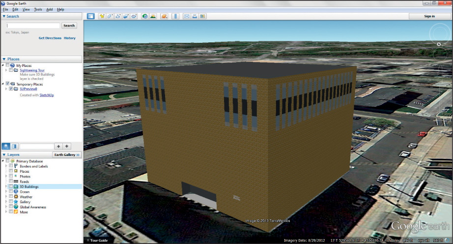 (Source: Google)
14.14 Saving Your Work (and Working On it Later)
- You can save your work at any time in SketchUp by selecting Save from the File pull-down menu.
- You can reopen your SketchUp model to work on it later by choosing Open from the File pull-down menu.
Closing Time
This lab was involved, but it served to show off many of the 3D modeling features available within SketchUp, and dealt with how to interface SketchUp together with GE. Exit SketchUp by selecting Exit from the File pull-down menu. Make sure you saved the final version of your SketchUp model, and the KMZ version of it as well.
Final SketchUp Modeling Checklist
____ Obtain overhead view of Lincoln Building and place it in SketchUp
____ Digitize building footprint
____ Extrude building to proper height
____ Set building properly on the terrain
____ Create entranceway opening on front of building
____ Create components for windows
____ Apply windows to all sides of building
____ Apply appropriate colors and textures to all faces
____ Create 3D text on front of building
____ Add other features (front columns, windows, roof unit)
____ Place 3D model in appropriate place in GE