1.3 1.2 Finding Euler Circuits
Now that we know what an Euler circuit is, we are faced with two obvious questions:
- Is there a way to tell by calculation or logical reasoning, not by trial and error, if a graph has an Euler circuit?
- Is there a method, other than trial and error, for finding an Euler circuit when one exists and finding it quickly?
Loosely speaking, the first question lies within the concerns of mathematicians because it asks whether or not a certain problem admits a solution. Typically, the second question lies in the domain of computer science because it concerns finding the actual answer to a complex version of a problem in a short enough time to be useful.
Euler investigated these questions in 1735 by using the concepts of valence and connectedness.
Valence DEFINITION
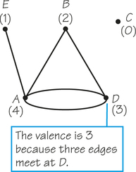
The valence of a vertex in a graph is the number of edges meeting at the vertex.
11
Figure 1.6 illustrates the concept of valence, with vertex A having valence 4, vertex D having valence 3, vertex B having valence 2, and vertex C having valence 0. Vertex E has valence 1. Isolated vertices such as vertex C are an annoyance in Euler circuit theory. Because they don’t occur in typical applications, we henceforth assume that our graphs have no vertices of valence 0.
Figure 1.3b has four vertices of valence 2, namely, A, C, F, and D. This graph also has two vertices, B and E, of valence 4. Notice that each vertex has a valence that is an even number. We’ll soon see that this is very significant.
Connected Graph DEFINITION
A graph is said to be connected if for every pair of its vertices, there is at least one path connecting the two vertices.
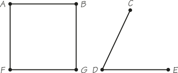
Given a graph, if we can find even one pair of vertices not connected by a path, then we say that the graph is not connected. For example, the graphs in Figure 1.6 and Figure 1.7 are not connected because we are unable to join A to C with a path of edges. However, the graph in Figure 1.7 does consist of two “pieces” or connected components, one containing the vertices A, B, F, and G, the other containing C, D, and E. A connected graph contains a single connected component. Notice that the parking-control graph of Figure 1.3b is connected.
We can now state Euler’s theorem, his simple answer to the problem of detecting when a graph G has an Euler circuit.
Euler Circuit Theorem THEOREM
- If G is connected and has all valences even, then G has an Euler circuit.
- Conversely, if G has an Euler circuit, then G must be connected and all its valences must be even numbers.
Because the parking-control graph of Figure 1.3b conforms to the connectedness and even-valence conditions, Euler’s theorem tells us that it has an Euler circuit. We already have found an Euler circuit for the graph shown in Figure 1.4b by trial and error. For a very large graph, however, trial and error may take a long time. It is usually quicker to check whether the graph is connected and even-valent as a way to be sure an Euler circuit must exist rather than produce a specific Euler circuit.
Once we know there is an Euler circuit in a certain graph, how do we find it? Many people find that, after a little practice, they can find Euler circuits by trial and error, and they don’t need detailed instructions on how to proceed. At this point you should see if you can develop this skill by trying to find Euler circuits in Figure 1.8a, Figure 1.9a, and Figure 1.10. In doing your experiments, draw your graph in ink and the circuit in pencil so you can erase if necessary.
12
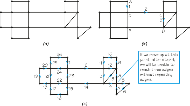
If you would like more guidance on how to find an Euler circuit without trial and error, here is a method that works: Never use an edge that is the only link between two parts of the graph that still need to be covered. Figure 1.9b illustrates this. Here we have started the circuit at A and gotten to D via B and C, and we want to know what to do next. Going to E would be a bad idea because the uncovered part of the graph would then be disconnected into left and right portions. You will never be able to get from the left part back to the right part because you have just used the last remaining link between these parts. Therefore, you should stay on the right side and finish that before using the edge from D to E. This kind of thinking needs to be applied every time you need to choose a new edge.
13
Let’s see how this works in Figure 1.9, starting at A. From vertex A there are two possible edges, and neither of them disconnects the unused portion of the graph. Thus, we could have gone either to the left or down. Having gone down to B, we now have three choices, none of which disconnects the unused part of the graph. After choosing to go from B to C, we find that any of the three choices at C is acceptable. Can you complete the Euler circuit? Figure 1.9c shows one of many ways to do this.
The method just described leaves many edge choices up to you. When there are many acceptable edges for your next step, you can pick one at random.
EXAMPLE 2 Finding an Euler Circuit
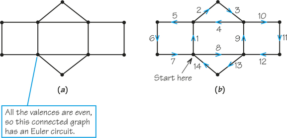
Check the valences of the vertices and the connectivity of the graph in Figure 1.8a to verify that the graph does have an Euler circuit. Now try to find an Euler circuit for that graph. You can start at any vertex. When you are done, compare your solution with the Euler circuit given in Figure 1.8b. If your path covers each edge exactly once and returns to its original vertex (which is a circuit), then it is an Euler circuit, even if it is not the same as the one we give.
Understanding Euler’s Theorem
We start by showing that if a graph has an Euler circuit R, then it must have only even-valent vertices and it must be connected. Let X be any vertex of the graph. We will show that the edges at X can be paired up, and this will prove that the valence is even. Every edge at X is used by R as an outgoing edge (leaving from X) or an incoming edge (arriving at X). If the Euler circuit starts at X, then pair up the first edge used by R with the last one (when the circuit returns to X for the last time). In addition, each other edge at X that is used by the circuit as an incoming edge will be paired with the outgoing edge that is used next. Because all edges at X are used by the Euler circuit, none more than once, this pairs up the edges. Hence, X must be even-valent because we have “organized” the edges of R in pairs.
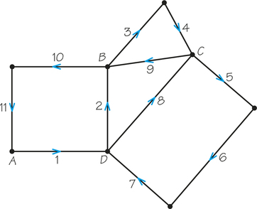
But what if X is not the start of the Euler circuit? If that is the case, do the pairing like this: The first incoming edge at X is paired with the outgoing one used next, the second incoming edge at X is paired with the outgoing one used next, and so on. For example, in Figure 1.11 at vertex B, we would pair up edges 2 and 3 and edges 9 and 10. At vertex C, we would pair up edges 4 and 5 and edges 8 and 9. Can you see how the pairings would work at D? How about vertex A?
14
In studying this example, you might think it would be simpler to count the edges at a vertex to see that the valence is even. True, but our pairing method works for a graph about which we know nothing except that it has an Euler circuit.
To see that a graph with an Euler circuit is connected, note that by following the Euler circuit around we can get from any edge to any other edge (it covers them all) using a portion of the Euler circuit. Because every vertex is on an edge (there are no vertices of valence 0), we can get from any vertex to any other using a portion of the Euler circuit.
So far, this is not a complete proof of Euler’s theorem. To complete the proof, we would need to prove that if a graph has all vertices even-valent and is connected, then an Euler circuit can be found for it. One way to do this is to piece together shorter circuits in the even-valent connected graph to get circuits using more edges.
Self Check 1
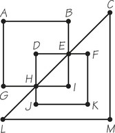
- How many vertices and edges does the graph in Figure 1.12b have?
- 8 vertices and 11 edges
- List the vertices in the graph that are even-valent (have even numbers for their valences).
- A, B, D, H, F, and E are even-valent.
- Is FEABFGCDHGF an Euler circuit for the graph?
- It is not an Euler circuit. One of the two edges joining B and F was not traversed; FG was traversed twice; edge BC was not traversed.