Chapter 2.
Overview of the Qubit® CO2 Analysis Package
The Qubit CO2 Analysis laboratory package may be used to measure photosynthesis, respiration, and photorespiration. Initially, the CO2 concentration in the gas provided to the chamber is measured with an infrared gas analyzer (IRGA), and then the gas is pumped through the chamber at a known flow rate. The concentration in the effluent gas from the chamber is measured using the IRGA, and the difference between this and the input gas is used to measure photosynthetic rate (or respiration rate if a greater CO2 concentration is measured in the effluent gas stream).
Components
AC Gas Pump
The gas pump samples air from the laboratory, or from a gas bag, and pumps this through the gas exchange system at a measured flow rate. The maximum flow from the pump is too great for direct use with the IRGA, so flow is attenuated by a needle valve on a flow meter attached to the pump’s outlet. The fittings on the outlet, and on the flow meter, ensure that connections can only be made in the correct direction.
The pump should be unplugged whenever it is not in use during an experiment, as this will significantly increase its operational life.
Gas Bags
The gas bags are made from a gas-impermeable nylon-polyethylene laminate and are heat-sealed. Tygon tubing is attached to each bag by a Luer-Lok fitting, and the fitting on the other end of the tubing attaches directly to the fitting on the leaf chamber. Once inflated, the bags should be sealed by capping the Luer-Lok fitting on the end of the Tygon tubing with the clamp. Bags should not be overinflated as this can cause weakening of the seams and eventual leakage. After use, bags should be fully deflated, preferably by attachment to a vacuum line.
Desiccant Column
It is recommended that all gases be dried thoroughly before entering the IRGA. To achieve this, a desiccant column is provided that is filled with Drierite. The Drierite contains an indicator that is blue when the column is functional and pink when the Drierite is spent. When spent, the Drierite should be replaced or reconditioned. To recondition, remove the Drierite from the column and place it in a drying oven at 80°C until the pink coloration disappears.
Flow Meter
The flow meter that is provided with this package has a range of 0–1000 mL/min. Attach the tubing on the flow meter inlet (at the bottom of the flow meter) to the tubing on the AC pump outlet and set the desired flow rate prior to attaching the flow meter outlet tubing to the gas analysis system. The AC pump is capable of providing flow rates of up to 2 L/min, but do not exceed a flow rate of 650 mL/min through the IRGA.
Read the flow rate at the maximum horizontal width of the spherical float. Multiply the numbers shown by 100 to obtain the flow rate. To adjust the flow rate turn the black knob clockwise (to decrease flow) or counter-clockwise (to increase flow). Do not unscrew the valve stem completely unless the flow meter is unpressurized, as serious injury may result.
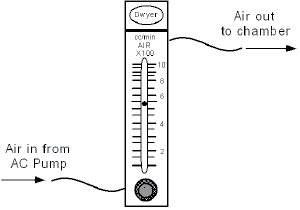
You must readjust the flow rate after attaching the flow meter to the gas analysis system because the back-pressure caused by the tubing and instruments will reduce the flow rate.
Serial Interface
Connects the CO2 analyzer to a computer to allow for computer-assisted data acquisition.
Qubit® Model S151 CO2 Analyzer
Introduction
The Qubit Systems S151 Carbon Dioxide (CO2) analyzer uses state-of-the-art nondispersive infrared technology (NDIR) to measure CO2 levels in a flowing gas stream.
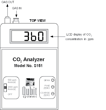
The instrument is equipped with a digital display that provides a measure of the CO2 concentration in units of parts per million (ppm). In addition, an analog output signal (0–5 VDC) is provided to allow the device to be monitored by a computer at either of two levels of sensitivity.
Operation
Using the CO2 Analyzer in a Gas Analysis System
The S151 IRGA has a gas input port with a female Luer-Lok connector and a gas outflow port with a male Luer-Lok connector. A length of Tygon tubing with a Luer-Lok connector is provided to join the S151 to the rest of your gas exchange system. The gas supplied to the S151 passes through its sealed analyzer chamber and vents from the outflow port. The S151 IRGA can be used in closed-circuit gas exchange systems and can be used with other gas analyzers downstream. However, you must ensure that the placement of an analyzer downstream from the S151 does not cause a significant increase in back-pressure. Increasing pressure significantly beyond that at which the analyzer was calibrated would cause erroneously high readings.
The maximum flow rate of gas into the instrument is 650 mL/min. This, or lower flow rates, should be provided by an external pump (AC and DC pumps, flow meters, and flow restrictors are supplied by Qubit Systems as optional extras). You should calibrate the IRGA at the flow rate that you intend to use during your experiments.
Gases entering the S151 must be clean and dry, since water vapor and particulate matter may absorb infrared light and cause erroneous readings.
Troubleshooting
The LCD Display Reads One (1)
This occurs during the warm-up period of operation. The S151 IRGA normally requires 2–3 minutes to warm up before it displays a value reflecting the CO2 concentration in the measurement tube. If the unit continues to display “1” after 5 minutes when the tube is being flushed with CO2-free air, contact Qubit Systems.
The LCD Readout Displays a Colon (:) Before the Numbers
A colon indicates a negative reading.
System Operation
Data Collection with LoggerPro
After about a five-minute warm-up, you are ready to begin collecting the data for your specific exercise. Refer to the specific exercise for details on this data collection.
Calculation of Generation/Consumption of CO2
The CO2 analyzer measures CO2 levels as parts per million (ppm). A conversion must be done to determine the micromoles of CO2 produced (or consumed) per liter of gas flowing through the system. The equation for this conversion is as follows:
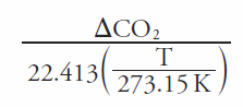
ΔCO2 = the change (increase or decrease) in reading compared to the reference amount of CO2 in ppm
T = the temperature in degrees Kelvin (temp. in K = temp in °C + 273.15 K)
The CO2 consumption/generation can be multiplied by the flow rate (in liters/sec) to get a rate of CO2 consumption/generation per second. If you measured the flow rate in mL/min, to convert to liters/second, divide by 60,000.
Typically, CO2 consumption/generation rates are expressed in terms of the surface area available. To convert the rate of CO2 consumption/generation into a rate per unit surface area, divide by the surface area in m2. If the surface area is known in cm2, it can be converted to m2 by dividing by 10,000.