3.4 How Is Data Transformed to a Georeferenced Format?
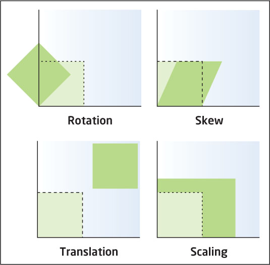
rotated when the unreferenced image is turned during the transformation
skewed when the unreferenced image is distorted or slanted during the transformation
scaled when the scale of the unreferenced image is altered during the transformation
translated when the unreferenced image is shifted during the transformation
affine transformation a linear mathematical process by which data can be altered to align with another data source
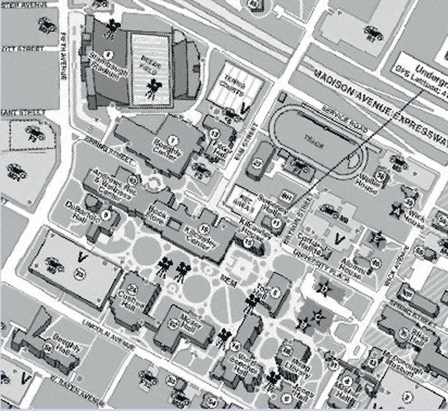
Take another look at Figure 3.3, which shows both the unreferenced campus map and the referenced source image. In order to make the unreferenced map align properly with the source image, there are a number of actions that have to be taken with the map. First, check out the football stadium (Stambaugh Stadium), which you’ll find in the upper left quarter of both the map and the referenced image. In order to match the basic position and alignment of the stadium as it appears on the map with the stadium in the image, it must be rotated about 45 degrees clockwise. As you look at the other features, it becomes clear that the whole map must be rotated by some amount, since the image is oriented to the north and the map is oriented to the northeast. It also becomes apparent that the map might have to be stretched or skewed to match up with the image.
66
When unreferenced data is transformed or “rectified”, it’s warped to make it match up with the source. It can be rotated (turned, like changing the orientation of the map), skewed (by pulling the image, like at a slant), scaled (by altering the entire map to match the image), and/or translated (by altering the location and placement of the map). See Figure 3.5 for examples of the effects of each of these transformations. This transformation of the data changes it to align with the new coordinate system. There are a number of transformation methods that are used, but a common one is the affine transformation, which will properly rotate, skew, scale, and translate the data.
The affine transformation calculates real-world X and Y coordinates for each unreferenced x and y coordinate. The formulae used for this are:
X = Ax + By + C
and
Y = Dx + Ey + F
where A, B, C, D, E, and F are the values calculated internally by the procedure and applied to the mathematical formulae as coefficients (and also control the properties like skewing and rotation). The affine transformation is a first-order transformation, and this is the type of transformation that’s usually utilized in this procedure. The end result of a transformation is that unreferenced data will be turned into spatially referenced data.
67
So, once you select some control points, the software runs the transformation and the data is georeferenced. Everything should work just fine. However, there are two questions that you should be asking yourself: “How do I know it worked?” and, more importantly, “How do I know the results are any good?” After all, just because the unreferenced data’s been transformed, it doesn’t necessarily mean that it’s a good match with the source. Since you know the coordinates of each place where you’ve put a control point, you should be able to match up those locations and see how closely your selected control points match the source. Figure 3.6 shows a report from a software program that measures error values for each control point.
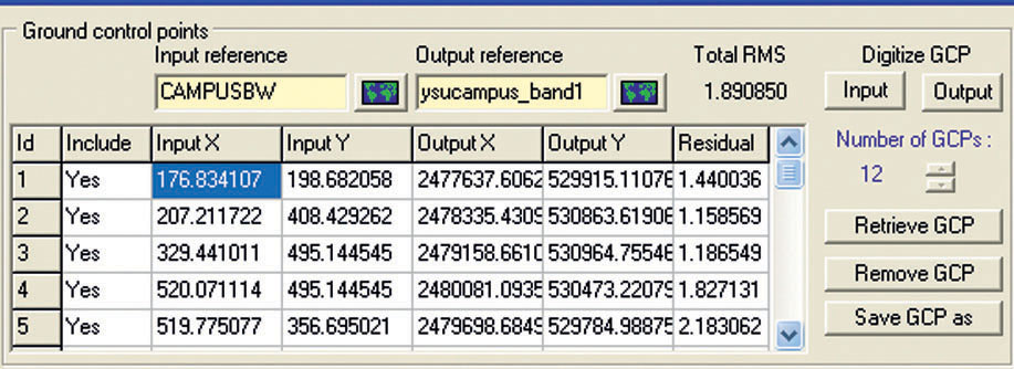
Root mean square error (RMSE) an error measure used in determining the accuracy of the overall transformation of the unreferenced data
A transformation procedure uses a value called Root mean square error (RMSE) as an indicator of how well the now-referenced data matches with the source. After the initial set of control points has been chosen and the unreferenced data is aligned with the source, coordinates are computed for locations of the selected control points. The known coordinate location of each control point (in the source) is compared with the newly computed value for its corresponding location in the unreferenced data. If the control points are in exactly the same location in both the unreferenced data and the source, then the difference in their coordinates will be zero. However, the chances are that when placing coordinates—even if you select good locations like road intersections—the two points aren’t going to match up exactly, though they might be very close. The software will examine all error values for all control points and report back a value for the RMSE.
The smaller the differences between where you put the control point on the unreferenced data (the estimated location) and its true location on the source data, the better the match between them will be. Thus, the lower the overall RMSE is, the better the transformation has worked. Usually, the georeferencing program will allow you to examine the difference between each point, so that you can see how closely your control point selections matched each other. If the RMSE is too high, it’s a good idea to check the difference in coordinates for each point—if a few of them are significantly off, they can be adjusted, changed, or deleted, and new points can be selected to try and get a better fit. If some parts of the data match well and others don’t, perhaps the control points need to be moved to other places to balance out the alignment better, or perhaps other control points need to be added, or maybe others need to be removed.
68
When you’re georeferencing an image, new locations for the image’s pixels will need to be calculated, and in some cases new values for the pixels will need to be generated as well. This process is referred to as resampling. The end result of a good georeferencing process will have your unreferenced data properly aligned with the source data (Figure 3.7). Maps that were not referenced can now match up with current maps and datasets (see Hands-on Application 3.3: Georeferenced National Park Maps and Hands-on Application 3.4: An Overview of the Georeferencing Process in ArcGIS for examples). Georeferencing can also be performed on other data created without a spatial reference, such as unreferenced drawings and plans. A related procedure can also be used for remotely sensed images that need to be corrected.
69
!search! THINKING CRITICALLY WITH GEOSPATIAL TECHNOLOGY 3.2
What Happens When the Georeferencing Is Wrong?
Think about this scenario. Surveying is being done for a new beachfront development, and a base map of the area will be created (using GIS) from current high-resolution remotely sensed imagery. Since the base map (and all layers created from it, such as property boundaries, utilities, and local land cover) will be derived from it, this initial layer is critical. However, something goes wrong in the georeferencing process of the image used to create the base map, and thus the initial base map has incorrect coordinates—and then each layer created from it has incorrect coordinates. When on-site GPS coordinates and measurements are reprojected to match the new base map, they’ll also be inaccurate since they use an incorrectly referenced base map. What’s going to be the end result of all this for the land owners, developers, construction crews, and others involved in the project? What kind of long-term or widespread problems could be caused by this type of “cascading error” when the initial referencing is incorrect?
!geo! HANDS-ON APPLICATION 3.3
Georeferenced National Park Maps
In this chapter’s lab you’ll be using a free software tool called MapCruncher, which will enable you to georeference your own images using Microsoft’s Bing Maps as the source. An example of the use of MapCruncher for georeferencing can be found here: http://research.microsoft.com/en-us/um/people/jelson/mapcruncher/gallery/nationalparks. Several park maps from the National Park Service have been aligned with and overlayed onto the Bing Maps interface. Zoom in to the now-georeferenced park maps and see how they match with the real-world imagery.
Expansion Questions:

Question
pFFfLqGtfhVqy8kbXvO8UFMqPXNbvBClHIDtHhzw3jzbgd/FRBKbvGkXHaCZE5ljMEeX+/OhRv0NxFf1M0egrN0JLgdiL+zQVpyC7k01f2JG1BMQxG6vR1+HspjH5aAEBByPdg==-
Question
NCKMMQ2K49ZaVpi6dARuFq2rJ7enKlTTFzDQdOLD/INzzb72wvx3uCu4+DacxEYoL0903rigmIlUEwxYysYSEbJFwlGuJlldYUBLBSkKGfkE7rewYioUom6G9uPWisHLAYBsfyAdurQgx5C70xA+hAHjigaHygfRVaIk/x83QIyS9d3VYtWTFyfozlcqJ6kBgmw17QBWi19vJCfE5N0KYHtN7mY3i8bl
70
!geo! HANDS-ON APPLICATION 3.4
An Overview of the Georeferencing Process in ArcGIS
While you’ll use the free MapCruncher to align unreferenced data in the lab, georeferencing tools are common in other GIS software (such as ArcGIS, which we’ll discuss further in Chapter 5). In order to demonstrate georeferencing in ArcGIS, the company has provided a video showing the whole process, step by step: http://video.arcgis.com/watch/376/georeferencing-rasters-in-arcgis. There’s also a second video which demonstrates how georeferencing can be performed automatically, without having to set up control points manually: http://video.arcgis.com/watch/1553/automatic-georeferencing-in-arcgis-101.
Check out both videos.
Expansion Questions:
-
Question
lYBP2vSTK1qTGPpaT7M1ZZroEHLY1Tirt2REUx7Brv7fHWSRGjTbARo0qqgBltQ6B3+UPL4EemPlIuQdV4vlCoprZ4e71FEQ0iS6jzhF0TgbRuGaklbtdg== -
Question
6MzstiTKNcjo4CtGxWN67pCLQZs8Nov1kQVNj6qa2R26z9cCIfw32IHU2tHGe4dj10eekqD8XFaDG+sUTzVx8xibo+wsJP4YQAaTws66hu7twOKRhMNfJw==