Chapter 1. Speed of Light
Objective

The objective of this experiment is to measure the speed of light in an optical fiber by measuring the time a light signal takes to traverse a known length of fiber.
Click the Next button to start this activity
Theory
If a light signal travels a length ΔL in a medium of refractive index, n in time Δt, then the constant speed of light in that medium can be determined simply as cn = ΔL/Δt. The refractive index of a medium is n = c/cn, where c is the speed of light in vacuum.
Experimental Details
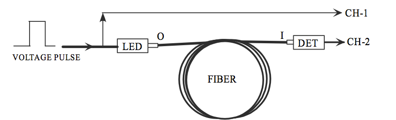
The basis of this experiment is very simple. An LED (light emitting diode) is energized by a square voltage pulse. The time, Δt of travel of the resulting light pulse emitted by the LED, through the fiber of length ΔL, is measured and used to compute the speed of light. But here is the caveat. Since Δt is only tens of nanoseconds, and the signals from Channel 1(CH-01) and Channel 2(CH-02) travel through different electrical paths considerable errors can be introduced in the measurement of Δt. Therefore, the actual experimental execution of the measurement scheme outlined above is a bit more interesting. Suppose you tap the square pulse signal (divert part of it) at the input end of the LED and use its detection as t = 0.0sec. It is instructive to know the various time delays that can be introduced before the signals of CH-01 and CH-02 are detected and displayed on the oscilloscope.
We have to make sure that the time delay we are measuring is only the time delay caused by the light traveling from O to I through the fiber and not due to any other electrical delays. The time delay between CH-01 and CH-02 can be expressed as ΔT =Δt +Δt’ where Δt is the time light takes to travel through the fiber and Δt’ is the total differential time delay between CH-01 and CH-02 due to different electrical paths the signals travel through the two channels. In most experiments such differential time delays are of little concern and are often neglected. However, in the present experiment Δt ~100 ns and Δt’ has to be properly compensated for. To do this we have to calibrate the time axis, as detailed below, by finding ΔT when Δt ~ 0. This is done by using a short length (15cm) of an optical fiber and measuring ΔT. For a 15 cm fiber Δt ~ 0.75 ns and thus ΔT0 =Δt +Δt’ = 0.75ns +Δt’. Since the expected Δt ~ 100ns for a 20m fiber, ΔT0 = 0.75ns +Δt’ can be taken as a reasonably accurate measure of the differential electrical delay between CH-01 and CH-02. Thus if we subtract ΔT0 from our time delay measurements, we can extract the time the light signal takes to travel through a given length of optical fiber.
Apparatus
- A Speed of Light (SOL) Apparatus with an associated power supply.
- One each of a 15cm, 10m, and a 20m long fiber-optic cable.
- A 100-MHz oscilloscope with two oscilloscope probes.
Experimental Procedure
- Turn on the oscilloscope
- Under TRIGGER:
- Press Source – select 1
- Press Mode – select Auto
- Press Slope/Coupling –
- select the Up-Slope (↑)
- set Coupling to AC
- Under HORIZONTAL::
- Press Main/Delayed and set the following
- Horizontal Mode : Main
- Vernier : Off
- Time Ref : Cntr
- Adjust Time/Div knob until divisions are presented in increments of 50ns (displayed on upper-right of screen)
- Under VERTICAL::
- Adjust V olts/Div to 1 V olt/div for CH-01 and 0.5 V olt/div for CH-02. The scale (Volt/div) will be displayed on the upper-left of screen.
- Press the CH-01 button and set the following
- CH-01 : On
- Coupling : AC
- BwLim:Off
- Invert : Off
- Vernier : Off
- Probe : 1
- Press the CH-02 button and apply the same settings as above for CH-01
- Adjust Position knobs until both CH-01 and CH-02 are at 0.00mv
- Attach oscilloscope probes to the lead-outs under the position knobs of CH-01 and CH-02
- Leaving the oscilloscope for now, turn your attention the SOL Apparatus. We will now begin the calibration of the SOL Apparatus.
- Set Calibration knob to the 12 o’clock position
- Using the 15cm fiber-optic cable, fit one end into the light blue D3 Transmitter
LED (the cable should fit snuggly). If the cable does not fit snugly (it easily slips out) you may gently tighten (no more than 1⁄4 to 1⁄2 turn) the fiber optic cinch nut.
CAUTION: Over tightening will result in damaging the cinch nut assembly. - Gently bend the fiber and insert the other end into the black D8 Receiver Detector DET
- Attach probe from CH-01 to SOL Apparatus on the Transmitter side
- Red → Reference
- Black → Ground
- Attach probe from CH-02 to SOL Apparatus on the Receiver side
- Red → Delay
- Black → Ground
- Plug power supply cable into SOL Apparatus (at the far left of the circuit). When power is applied to SOL Apparatus the yellow light at the top left should be lit.
- Returning our attention back to the oscilloscope:
- Under HORIZONTAL:
- Turn the Delay knob to the left or right until you see an obvious signal, there should be two – one for the trigger from CH-01 and one from the delayed signal from CH-02
- Adjust the Calibration knob on the SOL Apparatus until the peaks of both signals are aligned vertically
- Using the Horizontal Delay knob on the oscilloscope adjust the signals back to the center of the screen
The SOL Apparatus is now CALIBRATED!
- Disconnect the power supply from the wall socket. Carefully remove the 15cm fiber- optic cable from the SOL Apparatus and replace it with the 10m long. Once more, plug in the power supply.
- If you do not see an obvious signal on your screen, use the Horizontal Delay knob to locate it. The new signal should have a CH-02 output that is some distance from the original trigger signal.
- Measurement of Δt: Under MEASURE, select Cursors:
- On source 1
- select t1 – use the knob within the gray box containing the Measure buttons to move this cursor to the peak of signal 1 from CH-01
- select t2 by pressing the button below t2, adjust this cursor to the peak of the second signal
- Record the Δt between these two cursors given on the lower left hand part of the screen: Example: 51ns
- Remove the 10m fiber cable and replace it with the 20m cable. Determine Δt as in the step above. Record your readings in the Data sheet. Gently pull out the end of the 20m fiber that is connected to D8 Receiver Detector DET. Using a coupling sleeve, couple the free end of the 20m cable to a 10m cable. Slide the free end of the 10m cable into D8 Receiver Detector DET. Again, determine Δt as above.
Pre-Lab Assessment
Question 1.1
+bPbd33ldj37pYCRWN8BsjyXjCMh3RpEGTiT2GVgOcZwD5sFjBAT6cKA3l9yPwZgL4w3JDFYoY5DATsF/dYSakghPq+KtVC8dMTRA7BGXF/17EYMQuestion 1.2
76dQ/xPci/qFy1xFpWSGb1W9vJnQ98lQ140FKsPFhPn8rTibUEScsEeBxVM7qf2B66ClyUlmFd8h7Bb4OuZ2NgNQfARuo84lXeND2sQkg7dRS9k4dQth00nbjxAW+mG3uz0zDROoe3bxa3BqACQIkGC3YTBUEy+FJgEJiik3/YcoN2lcQuestion 1.3
KS5/StX/Dhp0GZ1bf4ftbqLr6mur3h65SC/Ixm5TziWzqzGnpB+LehErA9Sk8p1Iq49hujvEMPDjbdZ2MPqNRYgugT4+h2GxXorUHE86b04vQbgzSPd08OW3ApTNbvYIik+cuHbXy+fhsOTIYc/g/N+ZFaDw0IuQData Report
Click here to download Data Report Printable PDF
JUST FOR THE FUN OF IT
Click here to open Just for the Fun of It PDF.