Basic Deformation Structures
Geologists use the simple geometric concepts and measurements described earlier in this chapter to classify features such as faults and folds into different types of deformation structures.
Faults
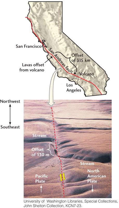
A fault is a fracture that displaces the rock on either side of it. We can measure the orientation of the fracture surface, or fault surface, by its strike and dip, just as we do for other geologic surfaces (see Figure 7.3). The movement of the block of rock on one side of the fault with respect to that on the other side can be described by a slip direction and by the total displacement, or offset. For small faults, such as the ones pictured in Figure 7.1b, the offset might be only a couple of meters, whereas the offset along a major transform fault, such as the San Andreas fault, can amount to hundreds of kilometers (Figure 7.7).
Rocks on either side of a fault cannot interpenetrate one another, and at high pressures below the surface, they cannot open up, so the slip direction during faulting must be parallel to the fault surface. Faults can therefore be classified by their slip direction along this surface (Figure 7.8). A dip-slip fault is one on which there has been relative movement of blocks of rock up or down the dip of the fault plane. A strike-slip fault is a fault on which the movement of blocks has been horizontal, parallel to the strike of the fault plane. When blocks of rock move along the strike and simultaneously up or down the dip, the result is an oblique-slip fault. Dip-slip faults are caused by compressive or tensional forces, whereas strike-slip faults are the work of shearing forces. An oblique-slip fault results from shearing in combination with either compression or tension.
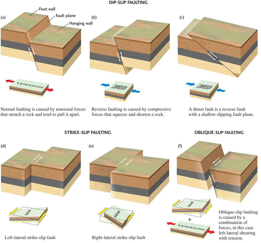
These fault types require further classification because the movement of rock can be up or down, or right or left. To describe these movements, geologists borrow some terminology used by miners, calling the block of rock above a dipping fault plane the hanging wall and the block of rock below it the foot wall. A dip-slip fault is called a normal fault if the hanging wall moves downward relative to the foot wall, extending the structure horizontally (Figure 7.8a). A dip-slip fault is called a reverse fault if the hanging wall moves upward relative to the foot wall, causing a shortening of the structure (Figure 7.8b)—the reverse of what geologists have (somewhat arbitrarily) chosen as “normal.” A thrust fault is a low-angled reverse fault—that is, one with a dip of less than 45°, so that the movement is more horizontal than vertical (Figure 7.8c). When subjected to horizontal compression, brittle rocks of the continental crust usually break along thrust faults with dips of 30° or less, rather than along more steeply dipping reverse faults.
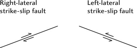
A strike-slip fault is a left-lateral fault if an observer on one side of the fault sees that the block on the opposite side has moved to the left (Figure 7.8d). It is a right-lateral fault if the block on the opposite side appears to have moved to the right (Figure 7.8e). As you can tell from the stream offset in Figure 7.7, the San Andreas fault is a right-lateral transform fault. Other faults show both strike-slip and dip-slip motions. These faults are known as oblique slip faults (Figure 7.8f).
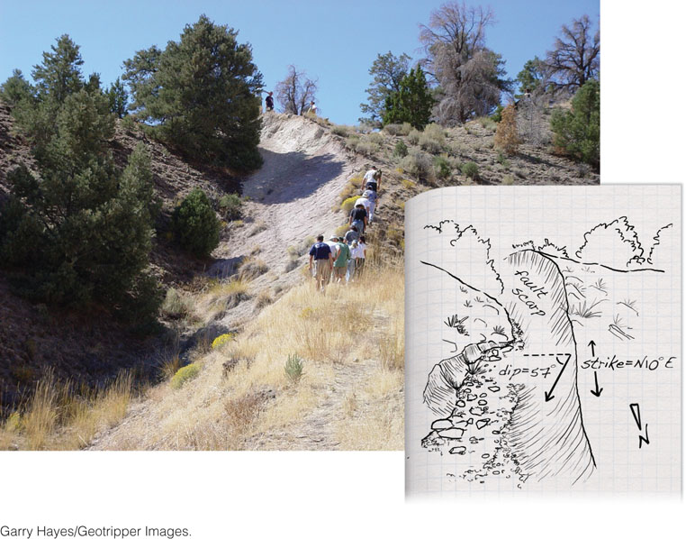
Geologists can recognize faults in the field in several ways. A fault may form a scarp (a cliff) that marks where the fault intersects the ground surface (Figure 7.9). If the offset has been large, as it is for transform faults such as the San Andreas, the rock formations facing each other across the fault may differ in type and age. When movements are smaller, offset features can be observed and measured. (As an exercise, try to match up the beds offset by the small faults in Figure 7.1b.) In establishing the time of faulting, geologists apply a simple rule: a fault must be younger than the youngest rocks it cuts (the rocks had to be there before they could break!) and older than the oldest undeformed formation that covers it.
178
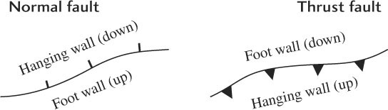
On geologic maps, faults are represented by fault traces: lines that indicate the point where a fault intersects the ground surface. Normal faults are distinguished from thrust faults by the different types of “teeth” that annotate the fault trace:
179
For both types of dip-slip faults, the teeth point toward the hanging wall. Examples of normal faults represented this way are shown in Figure 7.20; examples of thrust faults are shown in Figure 7.22. For strike-slip faults, the direction of movement, right-lateral or left-lateral, is indicated by a pair of arrows (yellow) that bracket the fault trace (see Figure 7.7):
Folds
Folding is a common form of deformation observed in layered rocks (as in Figure 7.1a). Folds occur when an originally planar structure, such as a sedimentary bed, is bent into a curved structure. The bending can be produced by either horizontally or vertically directed forces in the crust, just as either pushing together the opposite edges of a piece of paper or pushing up or down on one side or the other can fold it.
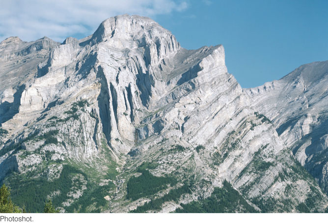
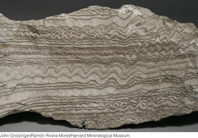
Like faults, folds come in all sizes. In many mountain belts, majestic, sweeping folds can be traced over many kilometers (Figure 7.10). On a much smaller scale, very thin sedimentary beds can be crumpled into folds a few centimeters long (Figure 7.11). The bending can be gentle or severe, depending on the magnitude of the applied forces, the length of time over which they were applied, and the resistance of the rocks to deformation.
180
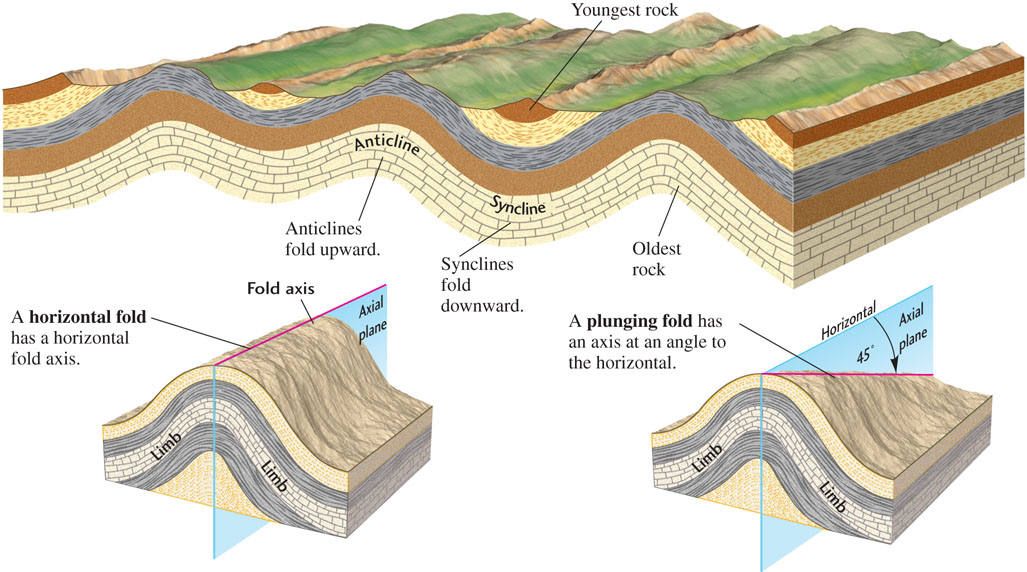
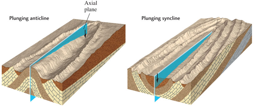
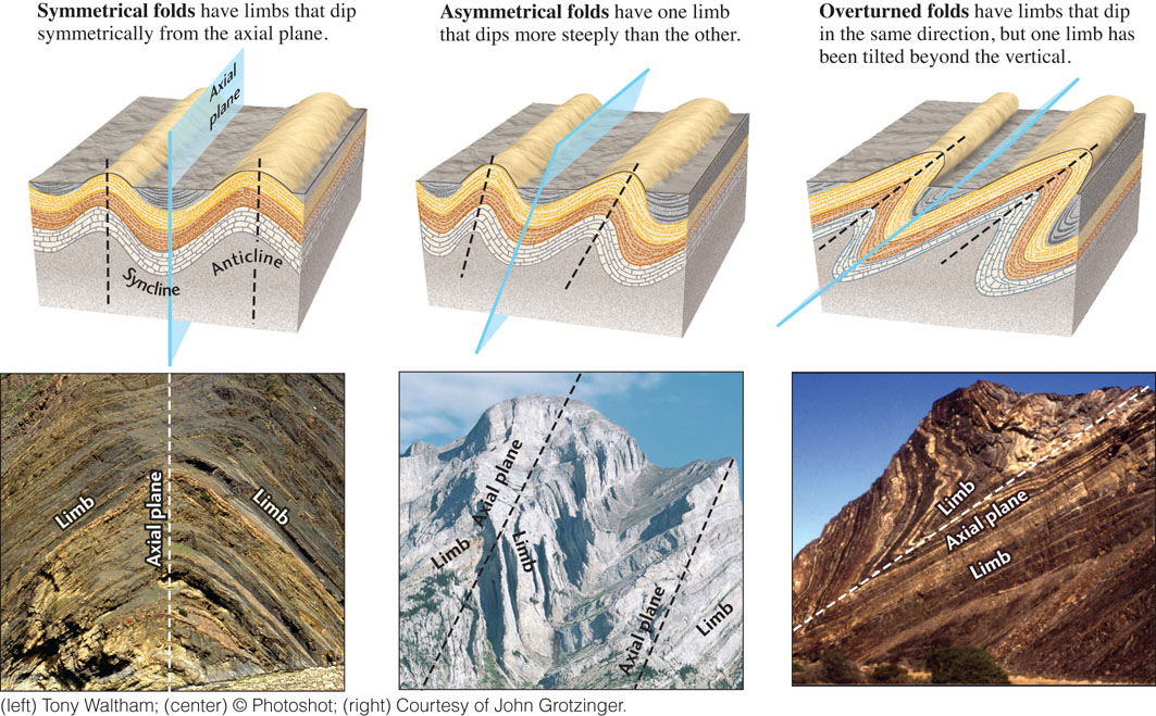
Folds in which layered rocks are bent upward into arches are called anticlines; those in which rocks are bent downward into troughs are called synclines (Figure 7.12). The two sides of a fold are its limbs. The axial plane of a fold is an imaginary surface that divides the fold as symmetrically as possible, with one limb on either side of the plane. The line made by the lengthwise intersection of the axial plane with the rock layers is the fold axis. A symmetrical horizontal fold has a horizontal fold axis and a vertical axial plane with limbs dipping symmetrically away from the axis.
181
Folds rarely stay horizontal, however. Follow the axis of any fold in the field, and sooner or later the fold dies out or appears to plunge into the ground. If a fold’s axis is not horizontal, it is called a plunging fold. Figure 7.13 diagrams the geometry of plunging anticlines and plunging synclines. In eroded mountain belts, a zigzag pattern of outcrops may appear in the field after erosion has removed much of the surface rock from the folds. The geologic map in Figure 7.4 shows this characteristic pattern.
Nor do folds usually remain symmetrical. With increasing amounts of deformation, folds can be pushed into asymmetrical shapes, with one limb dipping more steeply than the other (Figure 7.14). Such asymmetrical folds are common. When the deformation is so intense that one limb has been tilted beyond the vertical, the fold is called an overturned fold. Both limbs of an overturned fold dip in the same direction, but the order of the layers in the bottom limb is precisely the reverse of their original sequence—that is, older rocks are on top of younger rocks.
Observations in the field seldom provide complete information about folds. Bedrock may be obscured by overlying soils, or erosion may have removed much of the evidence of former structures. So geologists search for clues they can use to work out the relationship of one bed to another. For example, in the field or on a geologic map, an eroded anticline might be recognized as a strip of older rocks forming a core bordered on both sides by younger rocks dipping away from the core. An eroded syncline might appear as a core of younger rocks bordered on both sides by older rocks dipping toward the core. These relationships are illustrated in Figures 7.4 and 7.13. Determining the subsurface structure of folds by surface mapping has been an important method for finding oil, as described in the Practicing Geology exercise at the end of the chapter.
182
Circular Structures
Deformation along plate boundaries by horizontally directed forces usually results in linear faults and folds oriented nearly parallel to the plate boundary. Some types of deformation, however, are more symmetrical, forming nearly circular structures called basins and domes.
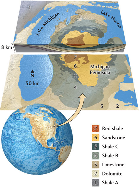
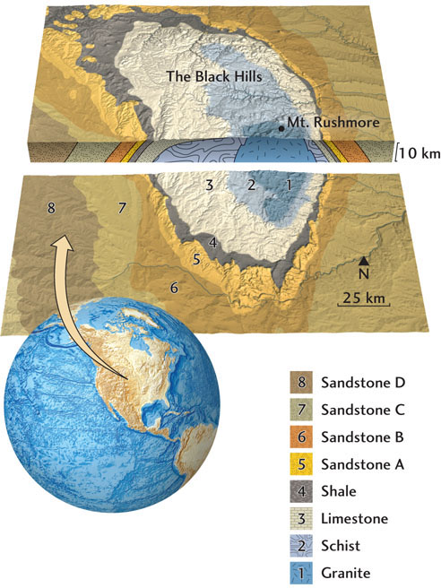
A basin is a synclinal structure, a bowl-shaped depression of rock layers in which the beds dip toward a central point (Figure 7.15). Sediments are often deposited in basins (see Chapter 5). In some cases, such as the Michigan Basin, shown in Figure 7.15, this deposition can produce sedimentary sequences many kilometers in thickness. A dome is an anticlinal structure, a broad circular or oval upward bulge of rock layers. The flanking beds of a dome encircle a central point and dip radially away from it (Figure 7.16). Domes, like other anticlines, are important in petroleum geology because oil is buoyant and tends to migrate upward through permeable rocks (see Practicing Geology exercise). If the rocks at the high point of a dome are impermeable to oil, the oil becomes trapped beneath them.
Domes and basins are typically many kilometers in diameter, and some extend for hundreds of kilometers. They are recognized in the field by outcrops that outline their characteristic circular or oval shapes. At these outcrops, the rock layers dip downward toward the center of the basin or upward toward the top of the dome (see Figures 7.15 and 7.16).
183
Some circular structures are formed by multiple episodes of deformation—for instance, when rocks are compressed in one direction and then again in a direction nearly perpendicular to the original direction. In many other cases, however, these structures result from the upward force of rising material or the downward force of sinking material, rather than the horizontally directed forces of plate tectonics. Not surprisingly, such circular structures tend to be more common in the interiors of plates, far away from active plate boundaries. There are many domes and basins, for example, in the central portion of the United States. Almost all of the Lower Peninsula of Michigan is a large sedimentary basin (see Figure 7.15); the Black Hills of South Dakota are an eroded dome (see Figure 7.16).
Several types of deformation can produce domes and basins. Some domes are formed by rising bodies of buoyant material—magma, hot igneous rock, or salt—that push the overlying sediments upward. As we saw in Chapter 5, some sedimentary basins form when a heated portion of the crust cools and contracts, causing the overlying sediments to subside (thermal subsidence basins). Others result when tectonic forces stretch and thin the crust (rift basins) or compress it downward (flexural basins). The weight of sediments deposited by a river delta can depress the crust into a sedimentary basin, such as the very large basin now forming at the mouth of the Mississippi River in the Gulf of Mexico.
Joints
As we have seen, a fracture that has displaced the rock on either side is called a fault. A second type of fracture is a joint—a crack in a rock formation along which there has been no appreciable movement (Figure 7.17a).
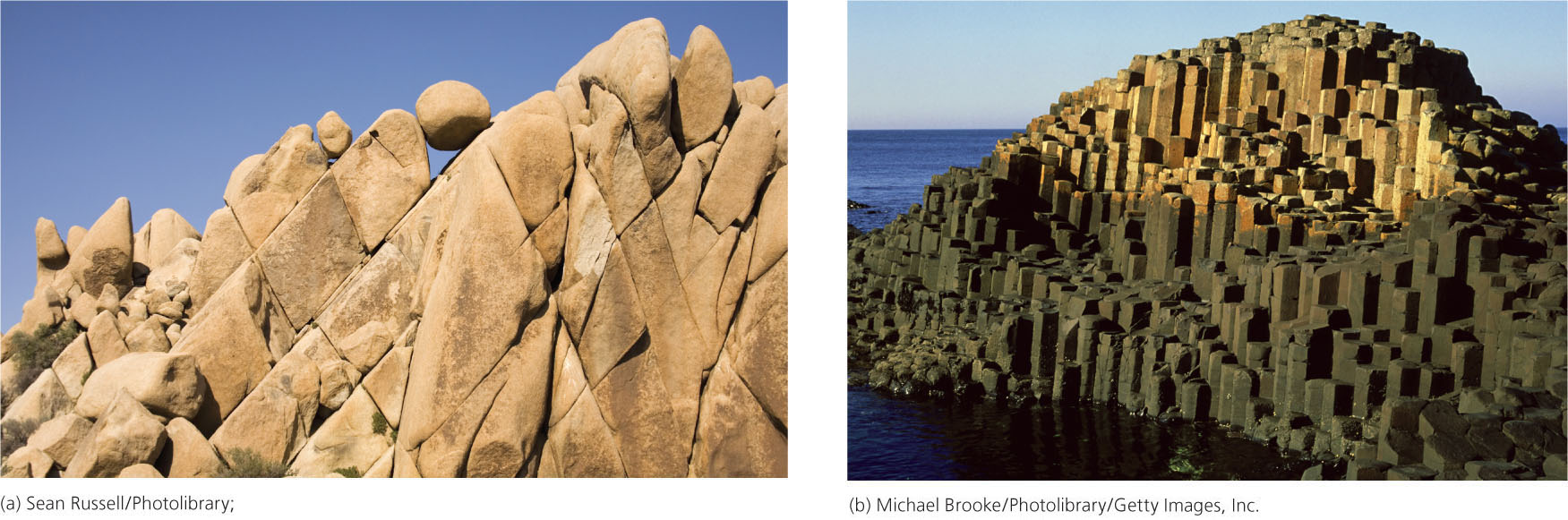
Joints are found in almost every outcrop. Some joints are caused by tectonic forces. Like any other brittle material, brittle rocks subjected to force fracture most easily at flaws or weak spots. These flaws can be tiny cracks, fragments of other materials, or even fossils. Regional tectonic forces—compressive, tensional, or shearing—may leave a set of joints as their imprint long after they have vanished.
The nontectonic expansion and contraction of rock can also form joints. Regular patterns of joints are often found in plutons and lavas that have cooled, contracted, and cracked. Erosion can strip away surface layers, releasing the confining pressure on underlying formations and allowing the rocks to expand and split at flaws.
Joints are usually only the beginning of a series of changes that greatly alter rock formations as they age. For example, joints provide channels through which water and air can reach deep into a formation and speed the weathering and internal weakening of its structure. If two or more sets of joints intersect, weathering may cause the formation to break into large columns or blocks (Figure 7.17b). The circulation of hydrothermal solutions through joints can deposit minerals such as quartz and calcite, forming veins, as we saw in Chapter 3.
Deformation Textures
Joints are examples of small features in rock formations that are best observed up close at an outcrop. Another type of small-scale deformation structure is the texture of a rock mass in areas of localized shearing, such as fault zones.
184
As we have seen, tectonic forces cause the brittle parts of Earth’s crust to crack and slip. As the rocks along a fault plane shear past each other, they grind and mechanically fragment solid rock. Where rocks behave as brittle materials (usually in the upper crust), shearing produces rocks with cataclastic textures, in which the grains are broken, angular fragments. One such rock type, called fault breccia, is shown in Figure 7.18a.
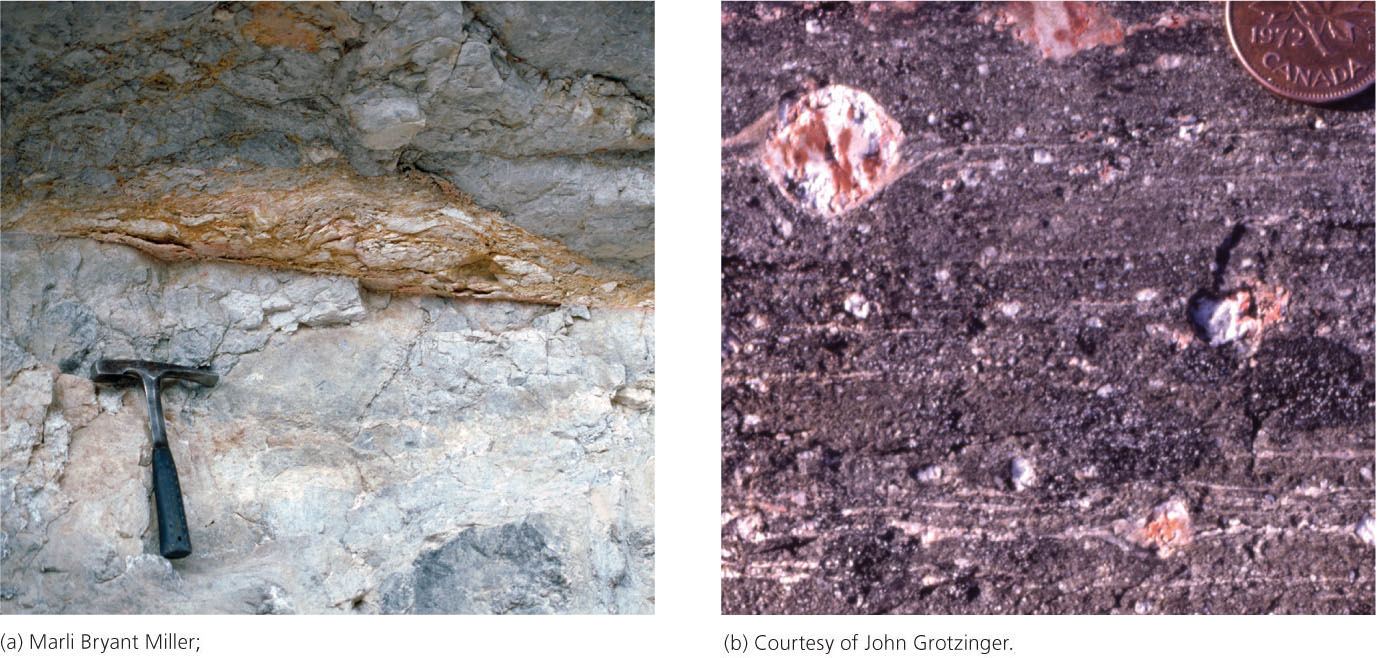
Deeper in the crust, where temperatures and pressures are high enough to allow ductile deformation, shearing forces can produce metamorphic rocks called mylonites (Figure 7.18b). The movement of rock surfaces against one another recrystallizes minerals and strings them out in bands or streaks. Development of mylonites typically occurs at the greenschist to amphibolite grades of metamorphism (see Chapter 6). The textural effects of deformation are most obvious in mylonites, but they are also prominent in cataclastic rocks.
The San Andreas fault of Southern California makes a good case study of how deformation textures might relate to changes in temperature and pressure with depth. This fault, which marks the boundary between the Pacific Plate and the North American Plate (see Figure 7.7), extends through the crust and probably down into the mantle. At depths up to about 20 km, the fault zone is thought to be very narrow and characterized by cataclastic textures, indicating brittle deformation. Earthquakes are generated in this zone. Below 20 km, however, earthquakes do not occur, and the fault is thought to be characterized by a broad zone of ductile deformation that produces mylonites.