Light-Sheet Microscopy Can Rapidly Image Cells in Living Tissue
Most of the confocal imaging approaches we have discussed above illuminate and detect fluorochromes through the same objective lens; this ensures that the excitation of the sample and the imaging of the emitted fluorescence occur in the same focal plane. As a result of this approach, there are limitations on the depth of sample that can be imaged. Very recently, a new technology has been developed to get around this limitation. In light-sheet microscopy, the sample is illuminated from the side and then viewed in an orthogonal direction (Figure 4-27a). A focused laser beam sweeps back and forth across the sample, illuminating a single plane. A detection objective, at right angles to the illuminated plane, then images the sample. To generate a three-dimensional image, all the planes in the sample have to be imaged. This is achieved by coordinately stepping the illuminating sheet and detection objective through the sample to generate a stack of images, which can then be assembled computationally into a three-dimensional rendering.
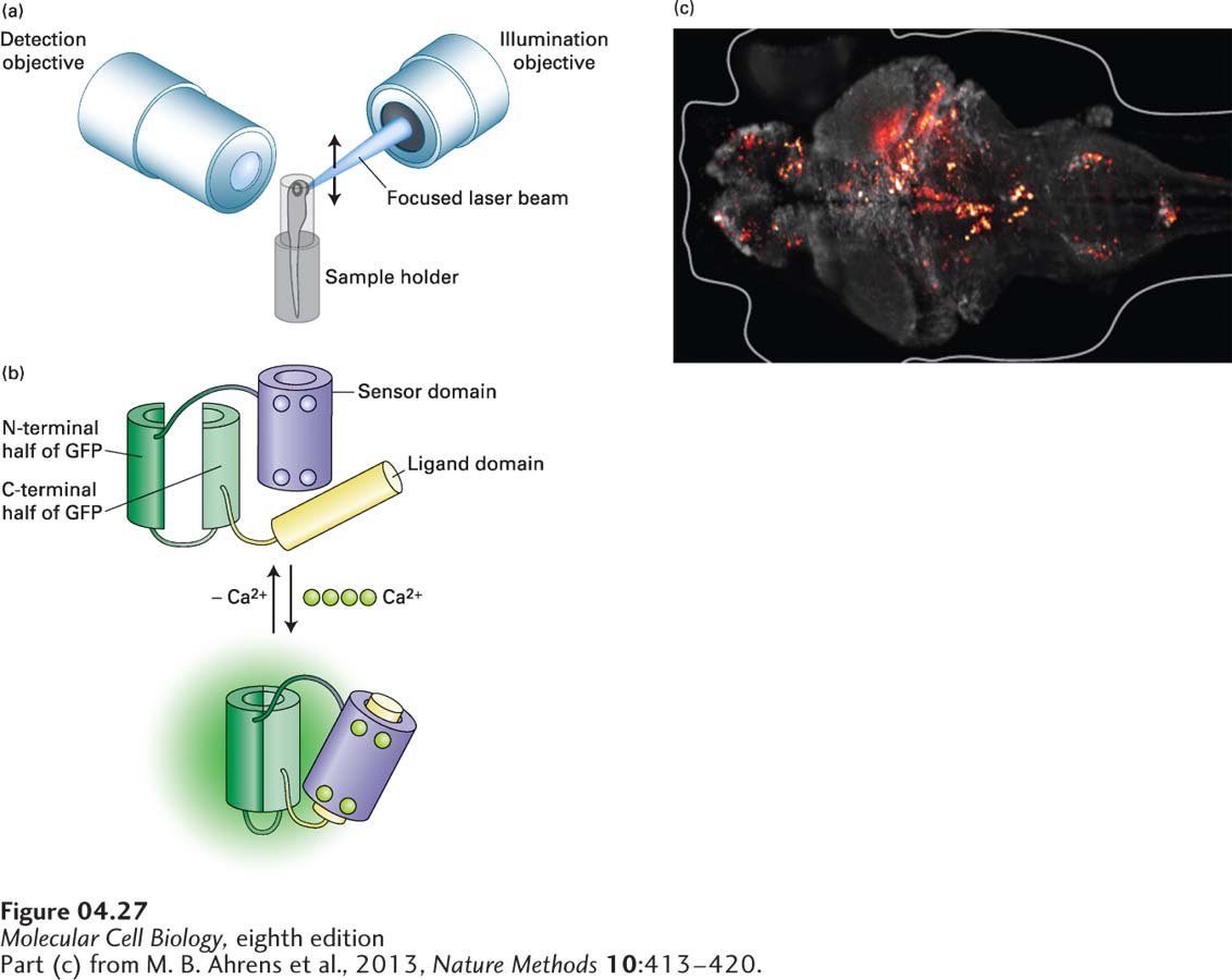
[Part (c) from M. B. Ahrens et al., 2013, Nature Methods10:413–420.]
FIGURE 4-27Light-sheet microscopy can image rapid events in living tissue. (a) In light-sheet microscopy, a tissue sample is illuminated from the side by a focused laser beam that scans the sample to generate a sheet of light. The sample is observed in the orthogonal direction though the detection objective. To get a three-dimensional image, the illuminating and detection objectives are moved coordinately, taking images throughout the depth of the sample. (b) The Ca2+ biosensor known as GCaMP. This biosensor is made using recombinant DNA techniques to generate a polypeptide to which the N- and C-termini of GFP are fused, and the middle interrupted. On one side of the interruption is the sensor domain, consisting of the Ca2+-binding protein calmodulin. On the other side is the ligand domain, consisting of a target sequence to which calmodulin will bind in the presence of Ca2+. In the absence of Ca2+, the GFP is not functional due to the interruption. In the presence of Ca2+, calmodulin binds four Ca2+ ions and undergoes a conformational change that allows it to bind the ligand domain. This conformational change brings the two parts of GFP into close proximity so that the fluorescent protein is functional. (c) Ca2+ transients, false-colored red, in cells of the brain of a living zebrafish.
[Part (c) from M. B. Ahrens et al., 2013, Nature Methods10:413–420.]
Page 156
In one example of the use of this technology, scientists have imaged concentrations of Ca2+ in the cells of a living zebrafish brain. The neurons in the brain of the zebrafish were made to express a Ca2+ biosensor, called GCaMP, which is based on GFP that does not fluoresce in the absence of Ca2+, but is designed to fluoresce in its presence (Figure 4-27b). This biosensor consists of GFP in which the N- and C-terminal domains are connected, but the middle of the protein is interrupted, and a Ca2+ sensor domain is attached to one end and a ligand domain to the other. Because the structure of GFP is interrupted, the protein no longer fluoresces when excited by the appropriate illuminating light. The sensor domain is derived from the small Ca2+-binding protein calmodulin (see Figure 3-31), which changes its conformation when it binds four Ca2+ ions. The ligand domain is a target sequence to which calmodulin binds only when it is activated by binding Ca2+. When active calmodulin binds the ligand domain, it changes the conformation of the interrupted GFP in such a way that it can now be excited and fluoresce. In this way, a fluorescent signal is reported whenever Ca2+ levels rise sufficiently to activate calmodulin. As we discuss in Chapter 22, when neurons communicate, part of this communication involves an elevation in Ca2+ levels. This neuronal communication can be nicely imaged by light-sheet microscopy in vivo in the brain of a zebrafish expressing the GCaMP biosensor (Figure 4-27c).