6-6 A radio telescope uses a large concave dish to reflect radio waves to a focus
For thousands of years, all the information that astronomers gathered about the universe was based on ordinary visible light. In the twentieth century, however, astronomers first began to explore the nonvisible electromagnetic radiation coming from astronomical objects. In this way they have discovered aspects of the cosmos that are forever hidden to optical telescopes.
Observing at radio wavelengths reveals aspects of the universe hidden from ordinary telescopes
Astronomers have used ultraviolet light to map the outer regions of the Sun and the clouds of Venus, and used infrared radiation to see new stars and perhaps new planetary systems in the process of formation. By detecting radio waves from Jupiter and Saturn, they have mapped the intense magnetic fields that surround those giant planets; by detecting curious bursts of X-rays from space, they have learned about the utterly alien conditions in the vicinity of a black hole. It is no exaggeration to say that today’s astronomers learn as much about the universe using telescopes for nonvisible wavelengths as they do using visible light.
Radio Astronomy
Radio waves were the first part of the electromagnetic spectrum beyond the visible to be exploited for astronomy. The use of radio waves is a result of a research project seemingly unrelated to astronomy. In the early 1930s, Karl Jansky, a young electrical engineer at Bell Telephone Laboratories, was trying to locate the source of interference with the then-new transatlantic radio link. By 1932, he realized that one kind of radio noise is strongest when the constellation Sagittarius is high in the sky. The center of our Galaxy is located in the direction of Sagittarius, and Jansky concluded that he was detecting radio waves from an astronomical source.
At first, only Grote Reber, a radio engineer living in Illinois, took up Jansky’s research. In 1936 Reber built in his backyard the first radio telescope, a radio-wave detector dedicated to astronomy. He modeled his design after an ordinary reflecting telescope, with a parabolic metal “dish” (reflecting antenna) measuring 10 m (31 ft) in diameter and a radio receiver at the focal point of the dish.
Reber spent the years from 1938 to 1944 mapping radio emissions from the sky at wavelengths of 1.9 m and 0.63 m. He found radio waves coming from the entire Milky Way, with the greatest emission from the center of the Galaxy. These results, together with the development of improved radio technology during World War II, encouraged the growth of radio astronomy and the construction of new radio telescopes around the world. Today, radio observatories are as common as major optical observatories.
Modern Radio Telescopes
Like Reber’s prototype, a typical modern radio telescope has a large parabolic dish (Figure 6-22). An antenna tuned to the desired frequency is located at the focus (like the prime focus design for optical reflecting telescopes shown in Fig. 6-11a). The incoming signal is relayed from the antenna to amplifiers and recording instruments, typically located in a room at the base of the telescope’s pier.
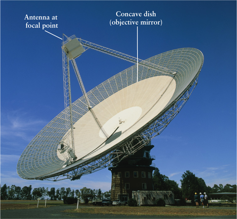
A Radio Telescope The dish of the Parkes radio telescope in New South Wales, Australia, is 64 m (210 ft) in diameter. Radio waves reflected from the dish are brought to a focus and collected by an antenna at the focal point.
CAUTION!
The radio telescope in Figure 6-22 looks like a radar dish but is used in a different way. In radar, the dish is used to send out a narrow beam of radio waves. If this beam encounters an object like an airplane, some of the radio waves will be reflected back to the radar dish and detected by a receiver at the focus of the dish. Thus, a radar dish looks for radio waves reflected by distant objects. By contrast, a radio telescope is designed to receive radio waves emitted by objects in space.
Many radio telescope dishes, like the one in Figure 6-22, have visible gaps in them like a wire mesh. This does not affect their reflecting power because the holes are much smaller than the wavelengths of the radio waves; the radio waves reflect from the wire mesh as if from a solid surface. The same idea is used in the design of microwave ovens. The glass window in the oven door would allow the microwaves to leak out, so the window is covered by a metal screen with small holes. These holes are much smaller than the 12.2-cm (4.8-in.) wavelength of the microwaves, so the screen reflects the microwaves back into the oven.
Radio Telescopes: Limits to Angular Resolution
One great drawback of early radio telescopes was their very poor angular resolution. Recall from Section 6-3 that angular resolution is the smallest angular separation between two stars that can just barely be distinguished as separate objects. Unlike visible light, radio waves are only slightly affected by turbulence in the atmosphere, so the limitation on the angular resolution of a radio telescope is diffraction. The problem is that diffraction-limited angular resolution is directly proportional to the wavelength being observed: The longer the wavelength, the larger (and hence worse) the angular resolution and the fuzzier the image. (See the formula for angular resolution θ in Section 6-3.) As an example, a 1-m radio telescope detecting radio waves of 5-cm wavelength has an angular resolution 100,000 times poorer than a 1-m optical telescope. Because radio radiation has very long wavelengths, small radio telescopes can produce only blurry, indistinct images.
 A very large radio telescope can produce a somewhat sharper radio image, because as the diameter of the telescope increases, the angular resolution decreases. In other words, the bigger the dish, the better the resolution. For this reason, most modern radio telescopes have dishes more than 30 m (100 ft) in diameter. A large dish is also useful for increasing light-gathering power, because radio signals from astronomical objects are typically very weak in comparison with the intensity of visible light emitted by the same objects. But even the largest single radio dish in existence, the 305-m (1000-ft) Arecibo radio telescope in Puerto Rico, cannot come close to the resolution of the best optical instruments.
To improve angular resolution at radio wavelengths, astronomers combine observations from two or more widely separated radio telescopes using the interferometry technique that we described in Section 6-3. Interferometry using radio waves is much easier than for visible or infrared light because radio signals can be carried over electrical wires. Consequently, two radio telescopes observing the same astronomical object can be hooked together, even if they are separated by a large distance, or baseline, of many kilometers. The connected radio dishes can act as a single large-diameter dish with vastly improved angular resolution.
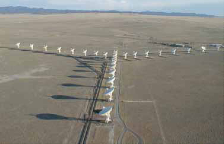
The Very Large Array (VLA) The 27 radio telescopes of the VLA in central New Mexico are arranged along the arms of a Y. The north arm of the array is 19 km long; the southwest and southeast arms are each 21 km long. By spreading the telescopes out along the legs and combining the signals received, the VLA can give the same angular resolution as a single dish many kilometers in radius.
One of the largest arrangements of radio telescopes for interferometry is the Very Large Array (VLA), located in the desert near Socorro, New Mexico (Figure 6-23). The VLA consists of 27 parabolic dishes, each 25 m (82 ft) in diameter. These 27 telescopes are arranged along the arms of a gigantic Y that covers an area 27 km (17 mi) in diameter. By pointing all 27 telescopes at the same object and combining the 27 radio signals, this system can produce radio views of the sky with an angular resolution as small as 0.05 arcsec, comparable to that of the very best optical telescopes.
Dramatically better angular resolution can be obtained by combining the signals from radio telescopes at different observatories thousands of kilometers apart. This technique is called very-long-baseline interferometry (VLBI). VLBI is used by a system called the Very Long Baseline Array (VLBA), which consists of ten 25-meter dishes at different locations between Hawaii and the Caribbean. Although the 10 dishes are not physically connected, they are all used to observe the same object at the same time. The data from each telescope are recorded electronically and processed later. By carefully synchronizing the 10 recorded signals, they can be combined just as if the telescopes had been linked together during the observation. With the VLBA, features smaller than 0.001 arcsec can be distinguished at radio wavelengths. This angular resolution is 100 times better than a large optical telescope with adaptive optics.
Even better angular resolution can be obtained by adding radio telescopes in space; the baseline is then the distance from the VLBA to the orbiting telescope. The first such space radio telescope, the Japanese HALCA spacecraft, operated from 1997 to 2003. Orbiting at a maximum distance of 21,400 km (13,300 mi) above Earth’s surface, HALCA gave a baseline 3 times longer—and thus an angular resolution 3 times better—than can be obtained with Earthbound telescopes alone. A Russian-led mission launched in 2011, Spektr-R, continues the effort for space-based interferometry.
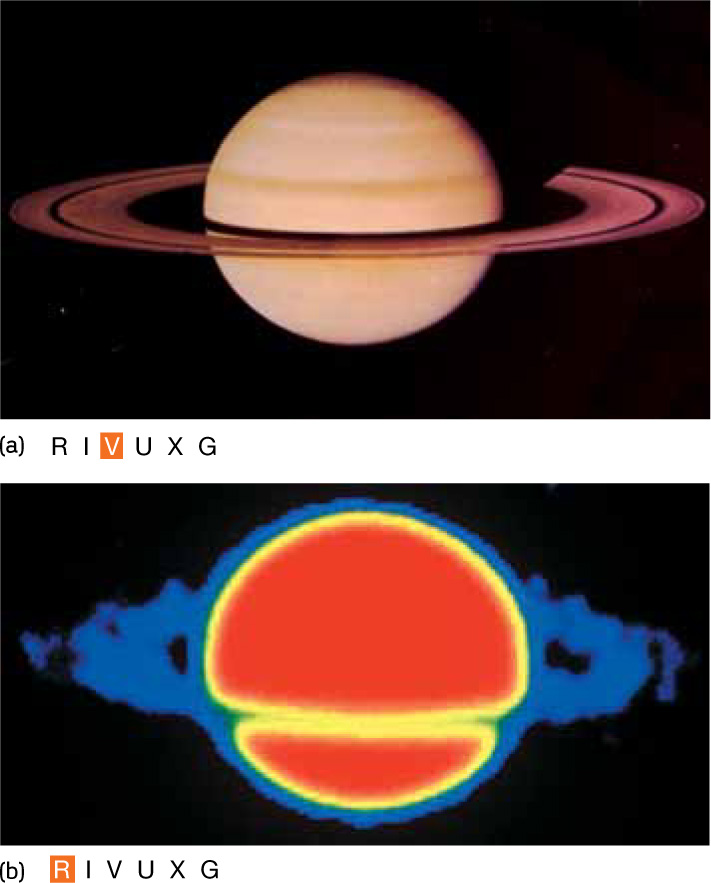
Figure 6-24 shows how optical and radio images of the same object can give different and complementary kinds of information. The visible-light image of Saturn (Figure 6-24a) shows clouds in the planet’s atmosphere and the structure of the rings. Like the visible light from the Moon, the light used to make this image is just reflected sunlight. By contrast, the false-color radio image of Saturn (Figure 6-24b) is a record of waves emitted by the planet and its rings. Analyzing such images provides information about the structure of Saturn’s atmosphere and rings that could never be obtained from a visible-light image such as Figure 6-24a.
CONCEPT CHECK 6-9
What radio telescope would make an image with the better resolution: a single radio antenna dish with a diameter of 100 m, or two 25-m dishes connected together at a separation of 200 m?
If more than one radio dish is connected together, the distance between the two dishes—not the size of the dishes—determines the telescope’s overall diameter when considering the angular resolution. Thus, two dishes at 200 m produce sharper images than a single 100-m dish.