7-3 Anatomical Imaging Techniques: CT and MRI
Tomo-
Until the early 1970s, the only way to actually image the living brain was by using X-
The CT method resembles the way in which our two eyes (and our brain) work in concert to perceive depth and distance to locate an object in space. The CT scan, however, coordinates many more than two images, roughly analogous to our walking to several vantage points to obtain multiple views. X-
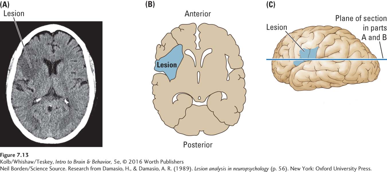
Figure 7-13A shows a typical CT scan. The dense skull forms a white border. The brain’s gray matter density does not differ sufficiently from that of white matter for a CT scan to distinguish between the two clearly, so the cortex and its underlying white matter show up as a more or less homogeneous gray. Ventricles can be visualized, however, because the fluid in them is far less dense: they, as well as some major fissures in the cortex, are rendered darker in the CT scan. Each point on the image in Figure 7-13A represents about a 1-

Neil Borden/Science Source
Section 10-4 delves into aphasias that result from damaged speech areas.
The lesion revealed in Figure 7-13A is a damaged region where the presence of fewer neurons and more fluid produces a contrast that appears as a dark area in the CT scan. This subject presented with symptoms of Broca’s aphasia, the inability to speak fluently despite having average comprehension and intact vocal mechanisms. The location of the lesion, in the left frontal cortex (adjacent to the butterfly-
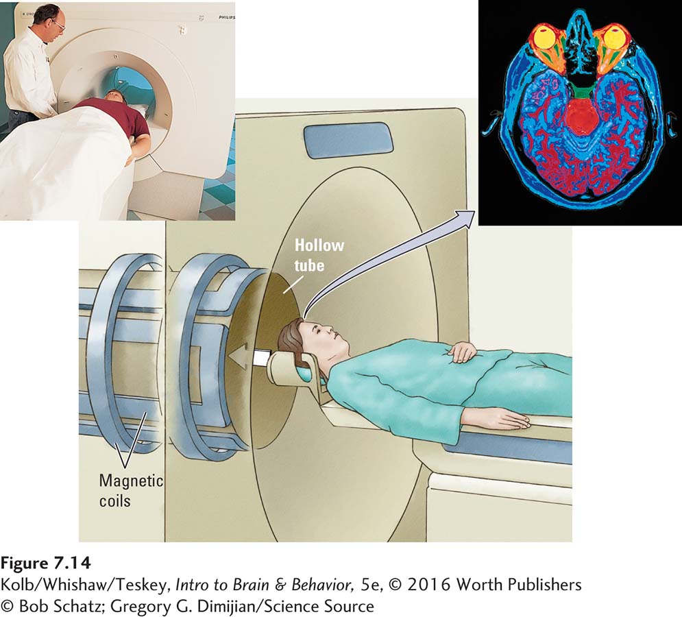
An anatomical alternative to the CT scan, magnetic resonance imaging (MRI), is based on the principle that hydrogen atoms behave like spinning bar magnets in the presence of a magnetic field. The MRI procedure is illustrated in Figure 7-14. The dorsal view of the brain portrays density differences among the hydrogen atoms in different neural regions as colors on the horizontal slice through the head.

Normally, hydrogen atoms point randomly in different directions, but when placed in a large, static magnetic field, they line up in parallel as they orient themselves with respect to the static field’s lines of force. In an MRI scanner, radio pulses are applied to a brain whose atoms have been aligned in this manner, and each radio pulse forms a second magnetic field. The second field causes the spinning atoms to deviate from the parallel orientation caused by the static magnetic field to a new orientation.
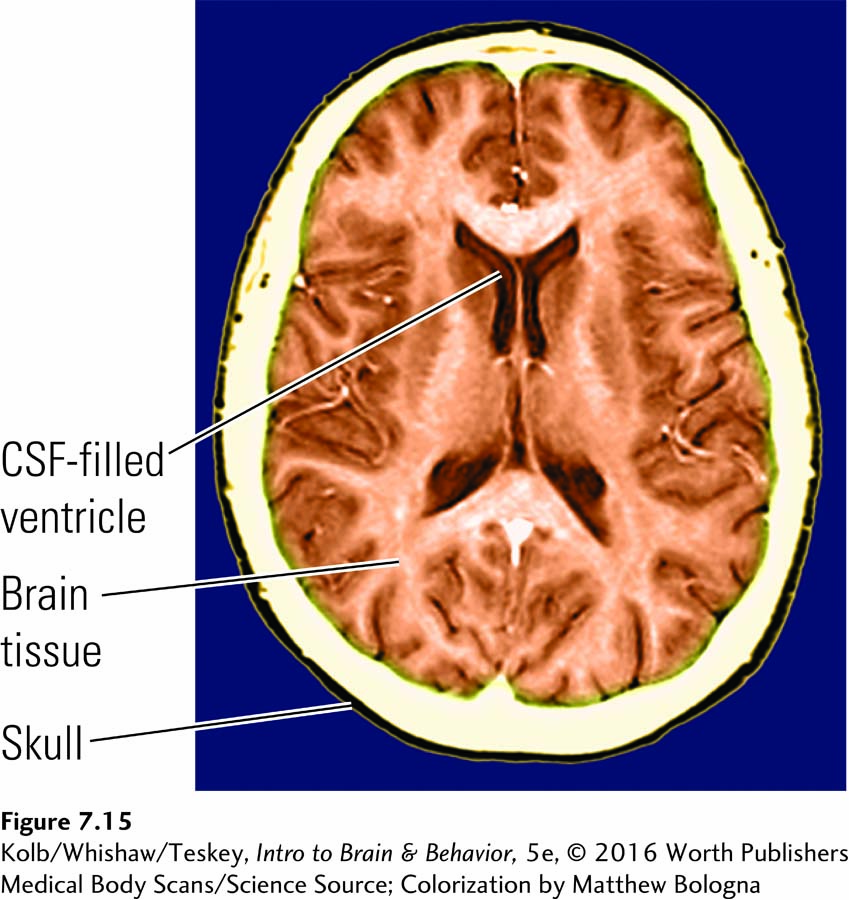
As each radio pulse ends and the hydrogen atoms realign with the static field, they emit a tiny amount of energy, and a coil detects this realignment. Based on the signals from the coil, a computer re-

Clinical Focus 4-2 describes how myelin loss in MS disrupts neuronal function.
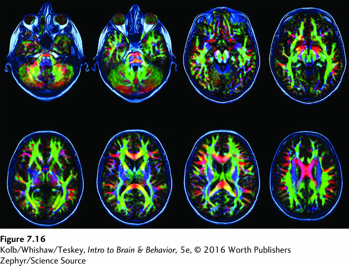
Diffusion tensor imaging (DTI) is an MRI method that detects the directional movements of water molecules to image nerve fiber pathways in the brain. Water can move relatively freely along the axon but less freely across cell membranes. The direction of this water movement is detected by a coil and interpreted by a computer. DTIs can delineate abnormalities in neural pathways. They are also used to identify changes in fiber myelination, such as the damage that leads to myelin loss in multiple sclerosis.
Focus 16-3 explores the relationship between concussion and degenerative brain disease.
Each scan in the series of DTIs shown in Figure 7-16 represents a dorsal view at increasing depths through the brain. Although the images appear to show real fibers, DTIs are virtual and based on computer reconstructions of water movement along axons, which should correspond to actual fibers. Nonetheless, DTI easily detects abnormalities, such as those that occur in multiple sclerosis, stroke, or concussion, in the imaged fiber pathways and in their myelin sheaths.

Magnetic resonance spectroscopy (MRS) is an MRI method that uses the hydrogen proton signal to determine the concentration of brain metabolites such as N-acetylaspartate (NAA) in brain tissue. This measurement is especially useful for detecting persisting abnormalities in brain metabolism in disorders such as concussion.
7-3 REVIEW
Anatomical Imaging Techniques: CT and MRI
Before you continue, check your understanding.
Question 1
The principal anatomical brain imaging methods are ________ and ________.
Question 2
Diffusion tensor imaging identifies ________, whereas magnetic resonance spectroscopy determines ________.
Question 3
In addition to imaging the density of different brain regions, CT and MRI can be used to assess ________.
Question 4
Explain briefly how the development of the CT scan ushered in the brain-
Answers appear in the Self Test section of the book.